

Python 网络自动化入门指南(四)
十、GNS3 基础
如果你不自己建造实验室,那么你就不知道实验室里的一切是如何工作的。建立你自己的虚拟实验室是掌握特定技术的最好方法之一。在本章中,您将学习如何使用 GNS3 和 VMware Workstation Pro 安装和构建一个简单的网络实验室。本章将指导您正确安装和配置 GNS3 的每个步骤,以充分利用您的设置。您还将了解 Windows 上 GNS3 的各种功能。如您所知,现在不需要基于硬件的网络设备。完成简单的实验拓扑后,您将集成一个旧的 IOS 映像,出于验证目的对实验进行测试,并熟悉实验设置。
在本章中,您将通过搭建简单的 IOS 实验室来学习 GNS3 基础知识。这里学到的 GNS3 技能将允许您在 GNS3 上构建各种网络自动化实验室。您可以将这些实验室的用途扩展到您的概念验证(POC)实验室或供应商网络认证工作中。
GNS3 概览
在第六章结束时,您下载了适用于您的 GNS3 版本的 GNS3
VM.ova文件,然后将其作为虚拟服务器导入,以托管您的网络设备。如果您尚未完成此任务,则必须返回并完成“从下载和安装 GNS3 VM”一节中详细介绍的任务。ova 文件。”然后回到这一章继续。
在本章和本书中,术语思科 CML 和思科 VIRL(或 CML 和 VIRL)可互换使用。它们基本上是在虚拟环境中模拟思科网络设备的相同软件。VIRL 代表虚拟互联网路由实验室,CML 代表思科建模实验室。CML 在 2020 年取代了 VIRL。
GNS3 是 2008 年推出的多厂商网络仿真器。受 Windows、Linux 和 macOS 支持,GNS3 也被称为图形用户界面(GUI) Dynamips。你只需要理解基于 GUI 的 GNS3 运行在 Dynamips 之上。GNS3 是在社区基础上开发和支持的,您可以在 GNS3.org 网站上注册用户后免费下载。对于本章,您需要最新版本的 GNS3,以便在 VMware Workstation 上将 GNS3 作为虚拟服务器运行。建议将 GNS3 作为虚拟机在 VMware Workstation Pro 上运行,这是我们实验室的最佳实践。当在主机操作系统上将 GNS3 作为本地服务器运行时,您的 Windows 性能会显著下降;在 VMware 工作站上将 GNS3 作为单独的虚拟机运行总是更好;这将防止主机 PC 和 GNS3 服务器之间出现任何 CPU 和内存争用问题。使用 GNS3 的另一个原因是用 Linux 虚拟机创建一个完全集成的实验室。您可以使用 Linux 服务器作为 Python 服务器来控制各种 PoC 实验室中的虚拟路由器和交换机,以研究和测试网络概念。
在 Windows 机器上安装 GNS3 时,你只需要一个安装.exe文件,但是在安装过程中会自动安装一些额外的软件。在安装过程中,您的计算机必须直接连接到互联网。本书中显示的安装过程包含了我多年来学到的技巧,建议您严格遵循每个步骤来完成本章中的所有任务。
要测试路由器、交换机或防火墙,您需要单独找到该软件,并将其快速集成到 GNS3 中用于各种实验。GNS3 不支持所有 IOS/IOS-XE/IOS-XR 版本;出于测试目的,它仍然支持较旧的 IOS 12.x 火车。虽然支持 Cisco 的 7200 路由器 IOS 15.x 版本,但 7200 路由器 IOS 15 . x 版本存在两个明显的问题;它占用计算机的 CPU 和内存资源,并且不支持第二层交换功能。思科的 IOU 已经提供给内部的思科 TAC 工程师,IOU 的副产品似乎是新的 VIRL L2 和 L3 网络研究软件。思科最近将 VIRL 更名为 CML 个人版(PE)。新的 CML-PE L2 和 L3 映像与之前的 VIRL 映像相同,因此在本书中,您可以使用思科的任何一个映像。
GNS3 为其他软件集成提供了更多有用的功能,对于网络学生和工程师来说,它是一个很好的学习工具。CME-PE、VIRL 和 IOU 图像支持使用 Qemu 作为新 GNS3 的主要功能。还支持通过 Docker 映像集成设备。没错,在 GNS3 中,Docker 和虚拟化程序可以在 GNS3 虚拟机服务器上并行运行。自从引入 IOU 和 VIRL 以来,配置此类实验设置的最大优势就是通过 L2 IOSv 镜像实现第 2 层交换功能。GNS3 继续支持 CML-PE 的 L2 IOSv 和 L3 IOS 映像。如果你想学习思科路由和交换,我强烈推荐使用思科 CML-PE 或 EVE-GN 实验室解决方案。如果你是 GNS3 的新手,你会喜欢本章的安装程序;大多数安装过程都很简单。如果您是 GNS3 的长期用户,那么您将在本章中学习各种安装和配置技巧,并提高您现有的 GNS3 集成技能。
第一章简要讨论了 GNS3,同时比较了用于网络研究的各种仿真和模拟工具。此外,我们还研究了每种工具的优缺点。在第六章的最后,你学习了如何从一个.ova文件构建一个虚拟机,即一个 GNS3 VM.ova文件是预装的虚拟机,用于更快的部署。作为虚拟机创建的一部分,您已经下载并创建了一个名为 GNS3 VM 的虚拟机。您已经慢慢掌握了 Python、虚拟化、Linux 管理和正则表达式方面的基本 IT 技能,为 Python 和网络自动化做好了准备。从本章开始,您将构建一个环境,在这个环境中,您可以使用 Python 学习、测试、验证和掌握各种网络自动化场景。
本章中的 GNS3 安装是我们在第六章中结束的地方的延续。让我们先安装 GNS3 来集成本章中的 Cisco IOS,然后将 CML-PE L2 和 L3 IOSv 软件与 Windows 主机 PC 和 Linux 虚拟机集成。
首次安装 GNS3
在第六章的 VMware Workstation 15 Pro 上创建虚拟机 GNS3 VM 是为 GNS3 与 VMware Workstation 和 Cisco 软件的集成做准备。思科的 IOS 和 VIRL 映像将由 GNS3 软件配置和控制,但实际的映像将从 GNS3 虚拟机运行,并在 VMware 工作站上运行。一个虚拟机在另一个虚拟机内运行被称为嵌套虚拟化环境。
在下载用于 Windows 10 的 GNS3 安装文件之前,请检查您的 GNS3 虚拟机的安装版本,并确保您下载的版本与您的 GNS3 虚拟机版本一致。如果你想要最新最好的 GNS3 版本,那么你可以从 GNS3 官方网站或 GitHub 网站下载 GNS3 安装文件和 GNS3 VM.ova文件。对于这本书,我已经下载了 2.2.11 版本的文件,这是在写本章时的最新版本。由于较新的 GNS3 软件定期发布,版本 2.2.11 或较新版本的 GNS3 将工作得很好。
下载 GNS3 安装文件
如果您尚未下载 GNS3 安装文件,则首先转到位于 https://github.com/GNS3/gns3-gui/releases 的 GNS3 下载 URL,并为您的 GNS3 VM 版本下载正确的 GNS3 .exe文件(参见图 10.1)。本书下载的版本是 2.2.11 ( GNS3-2.2.11-all-in-one.exe)。您可以放心地假设本书中使用的 GNS3 VM 版本也是版本 2.2.11,并且该虚拟机已经预安装在 VMware Workstation 15 上。如果您希望完全按照本书中的步骤操作,您可以使用相同的软件版本,但是如果您使用的是 VMware Workstation 16 Pro 和最新的 GNS3 文件,安装和设置过程将几乎完全相同,因此您不应该在设置 GNS3 环境时花费太多精力。
图 10-1。
用于 Windows 的 GNS3 安装文件下载
在这个例子中,使用 Assets 按钮通过开发者的 GitHub 网站下载软件。或者,在注册用户帐户后,可以从 GNS3.org 网站下载相同的软件。
GNS3 安装和设置
作为安装的一部分,GNS3 将安装基本软件,如 Microsoft Visual c++ 2017 re distributable(x64)、Wireshark、WinPcap 和 nPcap。假设你的电脑已经安装了必要的软件。在这种情况下,GNS3 安装向导将自动检测软件,但如果没有安装软件,它将自动安装必要的软件。在大多数安装情况下,GNS3 安装将顺利完成,但如果您的安装不顺利,您可以在 GNS3 安装之前预安装正确版本的 Wireshark、WinPcap 和 nPcap。您还将被提供注册和安装网络安全管理软件产品软件;在我看来,这是膨胀软件,所以如果你关心你的计算机的性能,确保你拒绝网络安全管理软件产品的免费提供。
GNS3 安装
最基本的安装任务已全部记录下来,并作为附加安装指南提供,以便在本书中包含更多高质量的内容。在 Windows 主机上安装 GNS3 非常简单,只需点击几次“下一步”按钮,直到安装完成。GNS3 的初始安装步骤请参考Chapter 10 Pre-task – Installing GNS3.pdf;安装指南可在 https://github.com/pynetauto/apress_pynetauto 获得。
下载并完成 GNS3 安装,然后继续下一部分!
GNS3 设置程序
现在我们必须设置 GNS3,以便您可以使用它来构建您的网络实验室。还有其他设置选项可用,但由于我们已经在 Windows 主机 PC 上导入了 GNS3 虚拟机,这将是我们首选的设置方法。按照说明操作,开始 GNS3 设置。
||
工作
|
| --- | --- |
| one | As soon as GNS3 launches, you will be prompted with the GNS3 server Setup Wizard. Here, we are using the GNS3 VM, so you must choose “Run appliances in a virtual machine.” Check the “Don’t show this again” box and click the Next button. See Figure 10-2.图 10-2。GNS3 设置,GNS3 服务器设置向导 |
| Two | Under “Local server configuration,” leave everything as the default. GNS3 on Windows uses TCP port 3080 for the server to localhost communication. This number is rarely altered unless you have an installation problem or want to configure it differently from out-of-the-box installation. Click the Next button again. See Figure 10-3.
图 10-3。GNS3 设置,本地服务器配置 |
| three | There is nothing to select for the local server status, so click the Next button to proceed. See Figure 10-4.
图 10-4。GNS3 设置,本地服务器状态 |
| four | The default GNS3 RAM recommendation is 2GB (2048MB); update this to 4GB (4096MB) or more based on your computer specification. My computer has 32GB memory, so my host will still have plenty of memory after allocating 8GB (8192MB) of memory to the GNS3 VM. If you have 16GB of memory, the recommendation is between 4GB and 6GB of memory to this VM. When you reset the memory allocation here, it will be reflected on VMware Workstation’s GNS3 VM server. If you are using an older CPU, leave the vCPU cores at 1, but if the CPU is newer, the vCPU cores can be increased to 2 or more. Click Next. See Figure 10-5.
图 10-5。GNS3 设置、GNS3 VM |
| five | As soon as you click the Next button, the GNS3 VM on the workstation will boot up. And once it goes through the Power-On Self-Test (POST) , you will see a blue welcome screen similar to Figure 10-6 on VMware Workstation 15 Pro. The GNS3 VM is a Linux (Ubuntu) appliance server configured to run various GNS3-compatible appliances from many vendors. GNS3 is a lot more than just a Cisco IOS emulator and has many use cases for studying other vendor products. Your GNS3 VM will be launched automatically; give it enough time to stabilize.
图 10-6。GNS3 设置,工作站上的 GNS3 VM 服务器已启动 |
| six | The GNS3 Setup Wizard summary window appears, and you can review and click the Finish button to complete your setup. See Figure 10-7.
图 10-7。GNS3 设置,设置摘要 |
| seven | Now you will see the GNS3 GUI with the GNS3 VM and your hostname (local host) with green status lights. If you see a red or amber light, it is an indication that your GNS3 installation has not been completed cleanly, and you may need to review your installation and setup processes and troubleshoot the issue. See Figure 10-8.
图 10-8。GNS3,第一次启动和运行 |
熟悉 GNS3
现在已经安装并启动了 GNS3,您可以开始使用该应用了。在进入 GNS3 并创建测试网络拓扑之前,让我们快速研究一下用户界面,以便更好地理解每个菜单的功能和选项。主下拉菜单选项中提供了所有图标菜单和更多菜单选项。以下部分是 GNS3 菜单的快速介绍和一些提示,可帮助您从 GNS3 顺利运行网络实验室。
GNS3 菜单和 GUI
图 10-9 显示了 GNS3 的主窗口,表 10-1 描述了每个选项。熟悉每个菜单的位置以及 GNS3 GUI 界面上最常用功能的图标位置,将有助于您在主机上使用 GNS3 时节省时间。
表 10-1。
GNS3 GUI 元素
||
菜单
|
说明
| | --- | --- | --- | | ① | 菜单选项 | 使用菜单访问下拉菜单中的所有选项。 | | ② | 文件选项 | 打开或保存 GNS3 项目。 | | ③ | 设备和拓扑选项 | 管理快照,显示/隐藏连接器,并控制设备。 | | ④ | 模拟选项 | 打开/关闭、暂停和重启设备。 | | ⑤号 | 绘图工具 | 用绘图工具装饰 GNS3 拓扑画布。 | | ⑥ | 设备类型图标 | 根据不同的设备类型显示设备。 | | ① | 添加链接工具 | 连接各种设备。 | | ⑧ | 设备列表 | 列出已安装的设备。使用搜索菜单过滤显示的设备。 | | ⑵ | 拓扑画布 | 在画布上选择并拖放设备,创建一个工作拓扑。 | | ⑩ | 日志窗口 | 显示 GNS3 操作状态。您也可以使用此窗口发送一些命令。 | | ⑪ | 拓扑/节点摘要 | 显示当前 GNS3 设备摘要。 | | ⑫ | 服务器摘要 | 显示 GNS3 虚拟机和本地服务器状态。此外,它还显示每台服务器的 CPU 和内存利用率。 |
图 10-9。
GNS3 GUI
正常关闭 GNS3 和 GNS3 虚拟机
在您开始在 GNS3 的拓扑画布上绘制图标之前,这是一个友好的提醒。由于 GNS3 对 Windows 安装的敏感性以及软件试图模拟物理硬件的方式,运行在 Windows 操作系统上的 GNS3 从来都不是 100%可靠的。为了避免麻烦和排除一些小问题的时间,我必须强调,当你在 Windows 操作系统上启动和关闭 GNS3 时,你应该采取更温和的方法。当您启动 GNS3 时,您必须给它足够的时间来启动其所有后台服务,如果您使用 GNS3 VM 来托管所有虚拟网络设备,还必须启动 GNS3 VM。最重要的是,在关闭 GNS3 时,您必须遵循一套严格的程序,以避免任何配置丢失,并避免由于应用突然关闭导致的文件损坏而删除整个项目。GNS3 是学习基本网络概念的最佳免费学习工具之一,但不幸的是,它不具备企业级的可靠性。
在完成 Cisco 或任何其他供应商的 GNS3 实验后,首先保存运行配置至关重要。对于 Cisco IOS 设备,运行copy running-config start-config或write memory将路由器或交换机的运行配置保存到启动配置。之后,使用红色大停止按钮或单独选择每个设备来关闭每个设备,使任何其他设备处于关闭状态(参见图 10-10 )。一旦保存了所有配置并且正确关闭了设备,那么您可以使用右上角的 X 优雅地关闭 GNS3(参见图 10-11 )。
图 10-10。
GNS3,使用右键单击选项停止设备
GNS3 关闭后,运行在 VMware Workstation 15 Pro 上的 GNS3 虚拟机也将自动关闭。最好不要从工作站关闭虚拟机;建议您使用右上角的 X 标记关闭 GNS3 应用。随着您对 GNS3 及其古怪之处的熟悉,这个关闭过程成为了一个标准程序。如果不小心,您的工作实验室配置和项目可能会由于不正确的关闭程序而经常出现故障。
图 10-11。
GNS3,使用 X 键正常关机
以管理员身份启动 GNS3
在 Windows 操作系统上首次启动 GNS3 时,这里有一个快速提示。当 GNS3 安装在您的 Windows PC 上时,如果您没有取消选择此选项,默认情况下将在您的 Windows 桌面上创建 GNS3 启动图标。使用此图标启动 GNS3 是启动程序的最快方式;但是,不以管理员身份启动 GNS3 会限制您对网络适配器设置和其他设置进行 GNS3 配置更改。因此,最佳实践是始终以管理员身份启动 GNS3。作为 GNS3 管理员,有一个小贴士可以改变 GNS3 图标下的设置。
||
工作
|
| --- | --- |
| one | First, go to the desktop of your host PC, locate the GNS3 icon, and right-click it to open Properties. See Figure 10-12.图 10-12。GNS3,Windows 主机桌面上的开始图标 |
| Two | Now, go to the Compatibility tab. Under Settings , select the “Run this program as an administrator” option, click the Apply button, and click the OK button to save the settings. See Figure 10-13.
图 10-13。GNS3,更改程序图标启动设置 |
现在你已经准备好学习一些 GNS3 技巧来提高你的技能。在本章的其余部分,将向您介绍一些很酷的 GNS3 技巧,例如将 GNS3 设备连接到主机、将 GNS3 连接到互联网、将 Microsoft loopback 添加到实验拓扑中,以及克隆 GNS3 项目以制作基础实验模板。
首次使用 GNS3:思科 IOS 和 Windows 实验室
最初,学习思科技术和认证的唯一方法是使用基于物理硬件的实验室,其中有一堆路由器和交换机。当 Christophe Fillot 在 2005 年 8 月开发 Dynamips 来模拟旧的 Cisco 路由器平台时,它永久性地改变了网络专业学生学习 Cisco 技术的方式。在 Dynamips 之前,有 Cisco 的 PacketTrace,但它更多的是一个模拟器,而不是仿真器。如前所述,GNS3 是 Dynamips 的 GUI 版本,GNS3 的底层应用仍然是 Dynamips。
最近,一个众所周知的秘密是 Cisco 正在使用基于 UNIX 的 Cisco IOU 进行内部员工培训,但是 IOU 并没有作为产品在市场上发布。有一段过渡期,思科 IOU 被泄露给思科合作伙伴,联网的同学都在用思科 IOU。思科最近将思科 IOU 重新解释为思科 CML(之前的 VIRL ),并将其发展为一种基于订阅的产品,可作为市场上的付费产品。
在 GNS3 开发人员集成 VIRL 和 IOU 映像之前,老派网络学生在 GNS3 上使用有点过时的思科 IOS 映像来学习思科认证。即使在今天,GNS3 也支持较旧的 Cisco IOS 映像;这与 CCNA 研究相关,因为它提供了不使用任何物理设备来模拟超过 90%的 CCNA 路由研究的方法。尽管网络技术和网络教育市场有了一些新的进步,但许多旧的路由和交换概念仍然与 CCNA 研究相关,因此在学习基本网络概念时,Cisco IOS 12.4.x 版本将足以满足您的学习需求。
使用旧的基于 IOS 的 GNS3 实验室学习网络有两个主要缺点。首先,它只能在大多数路由器平台上支持较旧的 IOS 12.4 版本,但 Cisco 7200 除外。其次,第 2 层对交换的支持只能通过安装在路由器平台上的 NM-16ESW 模块来实现。使用较新的 VIRL L2 和 L3 映像,您可以在 GNS3 上构建功能更多的思科路由和交换实验室,并具备许多 IOS 功能。
作为 GNS3 引入的一部分,将旧的 Cisco IOS 集成到实验室将是一个很好的起点。实际上,在 VIRL 集成中,唯一被替换的是 IOS 映像和更新的 VIRL 映像。本章将逐步向您介绍一些可以在运行于 GNS3 的 Cisco IOS 上使用的技术。在很大程度上,本章中学到的所有技术都可以扩展到第 12 、 13 和 14 章中的 CML 实验室,它们将帮助你建立各种更有效、更灵活的 GNS3 实验室。即使你是一名老 CCNA 学生,熟悉 GNS3 上的旧 IOS 集成,也不要跳过这一章,因为在这一章中你会学到一些新技能。
让我们先快速讨论一下思科软件许可模式,包括思科 IOS、IOU 和 VIRL 映像。
Cisco IOS 软件许可和下载旧的 Cisco IOS
首先,要使用 Cisco IOS 配置您的 GNS3 实验室,您必须找到并下载支持 GNS3 的 Cisco 路由器型号的 Cisco 互联网操作系统(IOS)映像。如前所述,这本书的工作假设要么你已经完成了思科 CCNA R&S 认证研究或你目前正在完成思科的助理级认证研究。另一个假设是,你对思科如何开展业务感兴趣,你想在未来的许多年里作为一名网络/安全/数据中心工程师在企业网络领域工作。思科通过销售硬件、软件和服务支持合同来增加收入。要了解思科如何通过软件增加收入,您必须了解思科软件的软件所有权和许可协议。要理解思科的软件许可模式,你必须从思科的商业模式着手。您已经知道,思科是面向企业和中小型企业市场销售网络设备的领先供应商;它出售其硬件和软件的技术支持合同包,以提高公司的利润率。技术支持协议还包括使用思科软件的权利。换句话说,如果您通过正规渠道从思科的合作伙伴那里购买了设备,那么作为客户,您有权使用在您的网络设备上运行的特定平台软件,并且如果您需要技术支持,可以获得思科 TAC 的全天候支持,直到服务合同的最后一天。
其次,请注意,如果您购买了运行 Cisco IOS 版本 15 的设备,通常您只允许在同一软件版本内进行较小的补丁升级,除非有安全漏洞的现场通知或升级到最新主要软件版本的现场通知。通常,您的设备会老化,新软件的最低硬件要求也会提高。你将被限制升级设备的软件到某个级别,你被迫升级到最新的硬件型号。随着思科设备即将停产(EoL),思科将不再支持任何 EoL 设备。思科的大部分软件被视为思科专有,是思科知识产权的一部分,因此思科拥有所有的 IOS 和其他软件权利;因此,不允许个人自由分发此软件。通过渠道合作伙伴购买思科设备后,技术支持服务合同还允许从思科 TAC 下载软件和获得技术支持。如果您目前为思科合作伙伴工作,您将能够轻松下载最新的 IOS 软件,但可能无法下载较旧的 IOS 软件。为你的研究获取旧 IOS 的另一个好方法是从易贝、Craigslist 或 Gumtree 等在线拍卖网站购买二手实验室路由器,甚至从你认识的不再使用他的旧 CCNA/CCNP 实验室设备的人那里购买。你会在你设备的闪存中找到一个正常工作的 IOS,IOS 可以通过 TFTP 文件传输复制到你的电脑上;那么它可以用作 GNS3 IOS 基础映像。即使您有权从思科网站下载 IOS,从思科的官方网站找到一个旧的 GNS3 兼容的 IOS 也是一个挑战,因为大多数旧设备已经停产。假设你是一名全日制学生,想从事网络行业,做网络或安全工程师。在这种情况下,谷歌搜索可以带你到一些网站,在那里你可能能够找到旧版本的 IOS。这本书使用了我的旧思科设备上的旧版本 IOS,但是最终下载旧版本 IOS 的工作副本是你的责任。
第三,当您访问 GNS3 的官方网站时,您将首先注意到 GNS3 支持较旧的思科路由器,即 C1700、C2600、C2691、C3600、C3700 和 C7200 系列路由器以及较旧样式的思科 PIX 防火墙。出于快速演示的目的,本章使用了旧的 Cisco 3725 路由器的 IOS 版本 12.4.15 T15,该版本与最新的 GNS 3.2.11 兼容。虽然支持 Cisco 7200 路由器的 IOS 版本 15.x,但 RAM 要求为 512MB,比旧的 3700 系列路由器消耗更多的计算机内存。如果您有一台 CPU 和内存相对较强的 PC,您可以选择使用 Cisco 7200 IOS 版本 15.x 来代替 3725 的 IOS。在本章中,使用的确切 IOS 版本是c3725-adventerprisek9-mz.124-15.T14.bin映像,这是 GNS3.2.11 当前支持的版本。
以下是一些旧版本的 IOS,您可以在我们的学习中使用:
-
c3725-adventerprisek9-mz.124-15.T14.bin(旧) -
c3745-adventerprisek9-mz.124-25d.bin(旧) -
c7200-adventerprisek9-mz.124-24.T5.bin(旧) -
c7200-adventerprisek9-mz.152-4.M7.bin(更新)
您负责购买和下载本书中所需的思科软件。本书不提供本书中使用的任何软件,但会向您指出查找和下载正确软件的来源。在一天结束的时候,每个读者都要为他们自己的学习需要对任何软件的使用负责。
解压缩 Cisco IOS 以供 GNS3 使用
如果你想跟随这本书,你应该已经成功地在你的Downloads文件夹中找到并下载了c3725-adventerprisek9-mz.124-15.T14.bin。然后,您将把.bin文件解压缩成.image文件,这样解压缩后的图像文件可以在 GNS3 中使用。在不同的操作系统上有不同的方法来解压缩 Cisco IOS .bin文件,但是您将学习如何使用两种最常见的 Windows 方法来解压缩 IOS 文件。第一种方法是使用Unpack-0.1_win.zip,第二种方法是将 GNS3 集成到 Dynamips 中对 IOS 进行解压缩。
使用 Unpack.exe 方法解压缩 Cisco IOS
在这里,您将为 Windows 下载Unpack.exe,并解压缩一个 Cisco IOS 文件供 GNS3 使用。按照这些简单的说明解压缩原始的.bin文件,并保存为一个.image文件,供 GNS3 使用。请注意,该文件必须以.image文件扩展名保存,并在本任务结束时移动到您 PC 的Downloads文件夹中。
|
工作
|
| --- | --- |
| one | 首先,下载Cisco image unpacker 0.1 binary for Windows到你的Downloads文件夹,并解压到Downloads文件夹下。文件名是Unpack-0.1_win.zip,可以从 SourceForge 下载。网。URL: https://sourceforge.net/projects/gns-3/files/Cisco%20Image%20Unpacker/v0.1/ |
| Two | If you still have your IOS file in the Downloads folder, move it to the Unpack folder, as shown in Figure 10-14.图 10-14。解压缩 IOS,将 IOS 文件移动到解压缩文件夹 |
| three | 在 Windows 命令行提示符下,运行下面的
unpack.exe命令将文件解压到同一个文件夹中。一旦文件被解压缩,解压缩后的文件名将使用.bin.unpacked作为其文件扩展名:unpack.exe --format IOS [Your_IOS_Name]。C:\Users\your_name\Downloads\Unpack>unpack.exe --format IOS c3725-adventerprisek9-mz.124-15.T14.bin注意用你的用户名替换your_name。 |
| four | Now rename the .bin.unpacked file as a .image file. So, the filename changes from c3725-adventerprisek9-mz.124-15.T14.bin.unpacked to c3725-adventerprisek9-mz.124-15.T14.image. Also, notice that the decompressed IMAGE file is almost twice the size of the .bin file. See Figure 10-15.图 10-15。解压缩 IOS,将解压缩的. bin.unpacked 文件重命名为。图像 |
| six | Once the filename has been updated with the correct file extension, copy and paste the file into the
Downloads folder again. This step is essential as GNS3 will be searching for a compatible .image file in the Downloads folder on your Windows. See Figure 10-16.图 10-16。解压缩 IOS,移动。图像文件到下载文件夹 |
如果您想了解如何使用第二种方法(Dynamips 方法)解压缩 IOS 文件,请阅读 10.4.2.2,但是如果您想立即开始网络实验构建任务,请跳到 10.5。
使用 Dynamips 方法解压缩 Cisco IOS(可选)
按照这些说明,使用 Dynamips 服务器方法将 IOS .bin文件解压缩到.image文件中。一旦你完成了任务,确保.image文件的副本已经放在你的主机的Downloads文件夹下。一些读者可能会发现这个过程比第一种解压方法更容易管理。
|
工作
|
| --- | --- |
| one | If you have not started your GNS3 and GNS3 VM, first launch it by double-clicking your desktop’s GNS3 start icon. See Figure 10-17.图 10-17。GNS3,GNS3 桌面图标 |
| Two | Give one to two minutes for the GNS3 VM to start up properly and settle down. Wait until both GNS3 VM and your local server’s CPU and RAM levels settle down. See Figure 10-18.
图 10-18。GNS3,服务器摘要窗口 |
| three | GNS3 will prompt you with the Project window. Since we are interested only in decompressing the IOS, we will click the Cancel button. See Figure 10-19.
图 10-19。GNS3,项目窗口取消 |
| four | To open the Preferences menu on GNS3, select Edit ➤ Preferences. See Figure 10-20.
图 10-20。GNS3,打开首选项菜单 |
| five | Select the IOS routers under Dynamips, as shown in Figure 10-21.
图 10-21。GNS3、dynamips、IOS 路由器 |
| six | Click the New button to open the New IOS router template window. In the Server screen, select “Run this IOS router on my local computer.” You can also select the “Run this IOS router on the GNS3 VM” option, but we’ll use the old method and remove the image after decompressing the file. See Figure 10-22.
图 10-22。GNS3,新的 IOS 路由器模板 |
| seven | In the IOS image window, click the Browse button on the right. See Figure 10-23.
图 10-23。GNS3,选择 IOS 映像 |
| eight | Select your IOS image in the
Downloads folder and click the Open button. See Figure 10-24.图 10-24。GNS3,选择 IOS 并打开 |
| nine | Click Yes to decompress the IOS image. See Figure 10-25.
图 10-25。GNS3,解压缩 IOS 映像 |
| Ten | 当你回到 IOS 镜像窗口时,GNS3 会告诉你
.image文件将被存储在哪里。在本演示中,它被提取到用户的GNS3\images\IOS\文件夹中。见图 10-26 。C:\Users\your_name\GNS3\images\IOS\c3725-adventerprisek9-mz.124-15.T14.image图 10-26。GNS3,解压缩图像位置注意用你的名字代替
your_name。 |
| Eleven | 对于名称和平台,将所有设置保留为默认值,然后单击 Next 按钮。 |
| Twelve | The recommended RAM size for 3725 is 256MB, but GNS3 will default the RAM to 128MB. This is only an example to demonstrate how to extract the .bin file into the .image file, so you can leave it as 128MB and click the OK button. See Figure 10-27.图 10-27。GNS3,内存 |
| Thirteen | 在“网络适配器”窗口中,单击下一步按钮。 |
| Fourteen | 在“WIC 模块”窗口中,再次单击下一步按钮。 |
| Fifteen | 在空闲 PC 窗口中,单击下一步按钮。参见图 10-28 。注意如果您选择在本地机器和 Dynamips 上运行 IOS 路由器,您可以单击 Idle-PC finder 按钮来查找合适的 Idle-PC,它会自动为您的系统找到一个最佳值。由于我们将配置 IOS 路由器从 GNS3 虚拟机运行,我们可以跳过这一过程。
图 10-28。GNS3,IOS idle-PC finder 示例 |
| Sixteen | Now we extracted the
.image file in a folder. We plan to run most of the devices on the GNS3 VM, so select the router and click the Delete button to remove the router from Dynamips ➤ IOS routers. Then, click OK to close the window. See Figure 10-29.图 10-29。GNS3,选择和删除 IOS 路由器 |
| Seventeen | 现在转到以下文件夹路径:
C:\Users\your_name\GNS3\images\IOS。您会发现扩展名为.image的解压缩 IOS 镜像文件的副本。将文件复制到Downloads文件夹。 |
Note
注意用你的用户名替换your_name。参见图 10-30 。
图 10-30。
主机,移动。图像文件到下载文件夹
现在,您可以在 GNS3 虚拟机上安装 Cisco IOS 路由器了。让我们坚持完成这项任务。
在 GNS3 虚拟机上安装 Cisco IOS
您已经成功解压缩了 IOS 映像,现在可以使用.image文件在本地服务器(PC)或 GNS3 VM 服务器上创建一个 GNS3 项目。由于我们使用 GNS3 VM 作为我们的 GNS3 服务器,并希望安装大多数设备,这避免了与本地 Dynamips 服务器设置相关的高 CPU 利用率、空闲 PC 和内存争用问题。我们将在 GNS3 虚拟机上安装 IOS,而不是本地服务器。这是一个推荐的安装,因为与在本地服务器上运行设备相比,GNS3 虚拟机的性能对主机性能的 CPU 和内存影响较小。
如果您的 GNS3 尚未运行,请启动应用,让它在工作站上初始化 GNS3 VM。等待大约 1 到 2 分钟,让 GNS3 虚拟机正常启动。等到你电脑的 CPU 和内存稳定下来。
假设工作站上的 GNS3 和 GNS3 VM 都在您的电脑上正常运行,让我们继续完成以下任务,创建我们的第一个 GNS3 项目,并在 GNS3 VM 服务器上安装.image文件:
|
工作
|
| --- | --- |
| one | 启动 GNS3 后,当 GNS3 项目窗口出现时,创建一个新的 GNS3 项目并命名。或者,您可以使用“新建项目”图标打开“项目”菜单并开始此任务。You can give any meaningful name of your choice. Here, the project name given was ios_lab. You do not have to follow this naming convention strictly. See Figure 10-31.图 10-31。GNS3,创建新项目 |
| Two | From the GNS3 menu, select File ➤ + New template. Or, click the Router icon under Devices on the left and click + New template. See Figure 10-32.
图 10-32。GNS3,打开“新模板”菜单 |
| three | When the “New template” window appears, select the "Install an appliance from the GNS3 server (recommended)" option. Click the Next button. See Figure 10-33.
图 10-33。GNS3,“新模板”选项 |
| four | Use the search field to locate your IOS device or use the drop-down device menu on the “Appliances from server” screen to select your device. Once you locate your IOS device, click it to select it and then click the Install button at the bottom. See Figure 10-34.
图 10-34。GNS3,搜索你的 IOS 设备 |
| five | Next, leave the “Server type” selection as the default, “Install appliance on the GNS3 VM (recommended),” and click the Next button one more time. See Figure 10-35.
图 10-35。GNS3,服务器类型选择 |
| six | If you have successfully followed the previous steps, the “Required files” window will locate your
.image file, and you will see the same or similar screen to Figure 10-36. Select the image file by highlighting the file and click the Next button again.图 10-36。GNS3,必需文件 |
| seven | Of course, you want to install the Cisco IOS on GNS3. Click the Yes button. See Figure 10-37.
图 10-37。GNS3,装置安装确认消息 |
| eight | You are almost there; click the Finish button to finish the installation. See Figure 10-38.
图 10-38。GNS3,使用提示 |
| nine | If the installation is successful, you will be prompted with the message shown in Figure 10-39. Click the OK button.
图 10-39。GNS3,添加模板成功消息 |
| Ten | 现在,让我们为 3725 分配正确的 RAM 大小,并为我们的实验室添加一个额外的 FastEthernet 接口。Finally, go back to the GNS3 main window and click the router icon. You will see the installed Cisco IOS router. Under the Routers icon, select the router icon and right-click and select “Configure template.” See Figure 10-40.
图 10-40。GNS3,配置模板 |
| Eleven | On the “Memories and disks” tab, change the default RAM size to 256MB and PCMCIA disk0 to the recommended 64MB and then click the OK button. You can go to the Cisco Feature Navigator page to check the RAM requirement for Cisco devices. You can go to
https://cfnng.cisco.com/archived-data and search for your platform and IOS version for older IOS devices. You can download the requirement in Excel format. See Figure 10-41.图 10-41。GNS3,将磁盘 0 添加到 IOS 路由器 |
| Twelve | On the Slots tab, add an NM-1FE-TX on slot 1. You can also add NM-4T for four more FastEthernet interfaces or NM-16ESW, which adds 16 L2 interfaces. If you want to use this router as an L2 switch, then NM-16ESW can be added, but this is an old GNS3 method with little relevance in the newer GNS3 labs. You can also add WIC-1T or WIC-2T under the WICs option on this tab. Since you are only going to connect through FastEthernet, you can leave the WIC slots blank. Click the OK button. See Figure 10-42.
图 10-42。GNS3,在 IOS 路由器上添加接口 |
| Thirteen | Now click the router icon and then drag and drop into the Topology canvas on the right. You have successfully installed an IOS image on the GNS3 VM. See Figure 10-43.
图 10-43。GNS3,检查安装 |
| Fourteen | Now close GNS3 by clicking the top-right X button to close GNS3 and the GNS3 VM running on Workstation. Your GNS3 will be closed, followed by GNS3 VM shutdown. If you have another virtual machine running on VMware Workstation, the other VMs on Workstation will continue to run. See Figure 10-44.
图 10-44。GNS3,关闭 GNS3(和 GNS3 虚拟机) |
在 GNS3 上创建 IOS 实验室拓扑并连接到互联网
|  | | 为了获得一致可靠的实验结果,本节涉及的任务需要互联网连接,建议您的计算机通过以太网电缆连接,而不是无线连接。实验室通过无线适配器连接可能会导致与书中不同的结果。在大多数情况下,实验都是通过将以太网电缆连接到家用路由器的以太网端口来进行的。学完本章后,大多数实验都可以通过无线连接正常工作,但是如果您怀疑某些地方工作不正常,请考虑将您的 PC 连接到路由器或交换机上的物理以太网端口。 |您被要求在 10.5 中关闭 GNS3 和 GNS3 虚拟机,我特意要求您关闭这些程序,以便您可以正确地重新打开之前的实验。现在,按照步骤重新打开项目,继续构建您的 IOS 实验室。
||
工作
|
| --- | --- |
| one | First, launch GNS3 using the GNS3 icon on your Windows desktop. When the GNS3 project window appears, wait for one to two minutes for the GNS3 VM to boot up. See Figure 10-45.图 10-45。GNS3,GNS3 桌面图标 |
| Two | Click the “Recent project” button under “Open project” to select the
ios_lab.gns3 project, and then click the OK button to re-open the first project. If the IOS installation and GNS3 integration were all OK, the project should normally open with a GNS3 VM kick-start on Workstation. See Figure 10-46.图 10-46。GNS3,打开最近的项目 |
| three | As soon as the
ios_lab.gns3 project opens, click the “All devices” icon on the left and drop one NAT (NAT1), two routers (R1 and R2), and two VPCS (PC1 and PC2). When you drag and drop these devices, you will be prompted to select a server to run these devices. Pay close attention to which server you select here. See Figure 10-47.图 10-47。GSN3,“所有设备”图标对于 NAT1,我选择
pynetauto,这是我的 PC 名;您的电脑名称会有所不同,因此您应该选择您的服务器名称。这意味着该设备将在本地服务器的 NATted 网络上运行,DHCP 服务将从 VMnet8 (192.168.183.0/24)网络中分配一个 IP 地址。You can also connect to the Internet via GNS3 VM’s NATted network (192.168.122.0/24), but connecting to the outside network via GNS3 VM sometimes could be unreliable. Using the local server NAT address via VMnet8 provides a more reliable connection to the Internet and the Linux servers running on VMnet8. See Figure 10-48.图 10-48。GSN3,NAT1 服务器选择 For routers and VPCSs, select GNS3 VM as the server. These devices will run on the GNS3 VM server. The GNS3 built-in service is usually used to provide a seamless virtual connection to other devices; it is not a managed switch like Cisco switches. VPCS is a handy GNS3’s built-in client, which allows the users to use them as end devices for simple ICMP tests. VPC saves a lot of computing power compared to running another virtual machine to run an end client. Using a VPC is like configuring a dummy loopback interface on a Cisco router or switch for end device reachability testing. Still, it is even better as you can still use ping and traceroute from VPCS, just like a real end device. See Figure 10-49.
图 10-49。GSN3、Switch1 和 PC1 服务器选择 |
| four | Click the “Add a link” icon on the left bottom, and connect all devices as shown in Figure 10-50. Refer to the Topology and Servers summaries to connect your devices as shown.
图 10-50。GSN3,连接设备 |
| five | When you are happy with your topology, click the big green play icon to start all devices. Note that if there are more than five devices, it is a best practice to right-click each device and start one device at a time to avoid the CPU and memory hangs during the device bootup. Once all devices have started, the lights on the connections should turn all green, as shown in Figure 10-51.
图 10-51。GSN3,起动装置 |
| six | Make sure that all lights under the Topology and Servers summaries are green and there are no errors. See Figure 10-52.
图 10-52。GSN3,拓扑状态 |
| seven | 要启动 R1 的控制台,只需双击拓扑上的 R1 图标,或者右键单击并选择控制台菜单。在控制台提示符下,让我们为第一个实验快速配置 R1。
| | eight | Now let’s configure R2. The configuration is similar to R1, but it has three interfaces on three different subnets . 【 T55
| `hostname R2``!` | Specify R2 as the host name | | `ip dhcp excluded-address 172.168.2.1``172.168.2.21` | | `!``ip dhcp pool VPCS_2``network 172.168.2.0 255.255.255.0` | 【 T70 DHCP is, 172.168.2.22 | | `interface FastEthernet0/0` | | | `ip address 192.0.2.2 255.255.255.0``no shut``!``interface FastEthernet0/1`【 T99 0/0 is configured with an IP addressconnected to f0/ of R1\. 1 portcalls out the interface | | `ip address 172.168.1.1 255.255.255.0``no shut``!`[ 7] | At f0/ 1 configure an IP addressto connect to PC1call-out interface | | `ip address 172.168.2.1 255.255.255.0``no shut` `!``router ospf 1``network 172.168.0.0 0.0.0.255 area 0` | in f1/ 0, configure an IP addressto connect to PC2call-out interface | | `network 172.168.2.0 0.0.0.255 area 0` 】`network 192.0.2.0 0.0.0.255 area 0``!` | Configure OSPF 1 | | `ip route 0.0.0.0 0.0.0.0 192.0.2.1` for internal network advertising. T171 】`!``!` | Configure the static route for the last selected gateway; The static route to R1 | | `do write memory` | saves the running configuration of R2 to the startup configuration||
| nine | 现在打开 PC1 (VPCS)控制台,练习手动配置 PC1 的 IP 地址。键入如下所示的命令。PC1> ip 172.168.1.11/24 172.168.1.1 <<< Assign IP address and Gateway``Checking for duplicate address...``PC1 : 172.168.1.11 255.255.255.0 gateway 172.168.1.1``PC1> ip dns 8.8.8.8 <<< Configure DNS IP address``PC1> show ip <<< Show ip address details``NAME : PC1 1``IP/MASK : 172.168.1.11/24``GATEWAY : 172.168.1.1``DNS : 8.8.8.8``MAC : 00:50:79:66:68:00``LPORT : 20000``RHOST:PORT : 127.0.0.1:20001``MTU: : 1500现在,通过从 PC1 向 R1、R2 和互联网发送一些 ICMP 消息来验证您的配置。PC1> ping 172.168.1.1 –c 3 <<< To the Gateway f0/1``172.168.1.1 icmp_seq=1 timeout <<< first arp drop``84 bytes from 172.168.1.1 icmp_seq=2 ttl=255 time=3.098 ms``84 bytes from 172.168.1.1 icmp_seq=3 ttl=255 time=8.093 ms``PC1> ping 192.0.2.1 -c 3 <<< To R1's f0/1``84 bytes from 192.0.2.1 icmp_seq=1 ttl=254 time=25.297 ms``84 bytes from 192.0.2.1 icmp_seq=2 ttl=254 time=29.232 ms``84 bytes from 192.0.2.1 icmp_seq=3 ttl=254 time=31.170 ms``ping 8.8.8.8 -c 3 <<< To Google DNS server, Ethernet connection recommended``84 bytes from 8.8.8.8 icmp_seq=1 ttl=126 time=50.198 ms <<< On wireless you may get timeouts``84 bytes from 8.8.8.8 icmp_seq=2 ttl=126 time=31.918 ms``84 bytes from 8.8.8.8 icmp_seq=3 ttl=126 time=58.199 ms |
| Ten | 这一次,打开 PC2 (VPCS)的控制台,使用ip dhcp命令配置 IP 地址。与之前的配置不同,PC2 将从 R2 的 DHCP 服务获取 IP 地址。如果您的配置完全相同,那么 PC2 的 IP 地址应该为 172.168.2.22。PC2> ip dhcp``DDORA IP 172.168.2.22/24 GW 172.168.2.1``PC2> show ip``NAME : PC2 1``IP/MASK : 172.168.2.22/24``GATEWAY : 172.168.2.1``DNS : 172.168.2.1``DHCP SERVER : 172.168.2.1``DHCP LEASE : 86391, 86400/43200/75600``MAC : 00:50:79:66:68:01``LPORT : 20002``RHOST:PORT : 127.0.0.1:20003``MTU: : 1500现在,通过从 PC2 向 R2、R1、PC1 和互联网发送一些 ICMP 消息来验证您的配置。PC2> ping 172.168.1.1 -c 3 <<< To R2’s f0/1 interface``84 bytes from 172.168.1.1 icmp_seq=1 ttl=255 time=4.515 ms``84 bytes from 172.168.1.1 icmp_seq=2 ttl=255 time=2.110 ms``84 bytes from 172.168.1.1 icmp_seq=3 ttl=255 time=5.558 ms``PC2> ping 172.168.1.11 -c 3 <<< To PC1, no entry in the ARP table.``172.168.1.11 icmp_seq=1 timeout <<< first arp drop``172.168.1.11 icmp_seq=2 timeout <<< second arp drop``84 bytes from 172.168.1.11 icmp_seq=3 ttl=63 time=12.709 ms注意:每当路由器必须向下一跳(或直接连接的目的地)发送没有 ARP 表条目的数据包时,ARP 请求会发出,但一个或两个原始数据包会被无条件丢弃。 |
| | PC2> ping 192.0.2.1 -c 3 <<< To R1’s f0/1``84 bytes from 192.0.2.1 icmp_seq=1 ttl=126 time=33.306 ms``84 bytes from 192.0.2.1 icmp_seq=2 ttl=126 time=27.037 ms``84 bytes from 192.0.2.1 icmp_seq=3 ttl=126 time=23.962 ms``PC2> ping 8.8.8.8 -c 3 <<< To Google’s DNS server``84 bytes from 8.8.8.8 icmp_seq=1 ttl=126 time=51.237 ms <<< On wireless you may get timeouts``84 bytes from 8.8.8.8 icmp_seq=2 ttl=126 time=35.299 ms``84 bytes from 8.8.8.8 icmp_seq=3 ttl=126 time=24.883 ms完成实验后,按照标准程序保存配置,关闭设备,并关闭项目。 |
您已经使用两台 Cisco IOS 路由器和两台 VPCS 完成了 GNS3 基本 OSPF 路由实验。虽然这不是一本关于路由和交换的书,但您已经建立了拓扑,配置了拓扑,并完成了以下任务:
-
为路由器接口分配 IP 地址
-
配置了名称服务器
-
在 R2 上配置了 DHCP 服务
-
在 R1 和 R2 上为内部路由配置了 OSPF
-
已配置的静态路由器(最后的网关)
-
将运行配置保存到启动配置
此外,您还学习了如何使用手动和 DHCP 配置方法来配置和使用 GNS3 的虚拟 PC (VPCS)功能。
接下来,让我们了解如何安装 Microsoft 环回适配器,通过从主机的 Windows 操作系统与 GNS3 拓扑通信来管理 GNS3 设备。Microsoft 环回适配器帮助 Windows 主机与运行在 GNS3 上的设备通信。
安装 Microsoft 环回适配器
要从主机 PC 通信、控制和管理运行在 GNS3 上的 Cisco 设备,您可以安装 Microsoft loopback 适配器,并与运行在 GNS3 上的 Cisco 路由器、交换机或其它设备通信。Microsoft loopback 适配器是用于测试目的的虚拟网络适配器,由 Windows 提供。借助 Microsoft loopback,您可以方便、可靠地从主机操作系统连接到 GNS3 设备,并与虚拟设备通信。以下是如何在你的主机上安装实验性的微软回环。假设你是一个重度 Windows 用户,需要一些时间来提高 Linux 管理技能。在这种情况下,从您的 Windows 主机访问和管理 GNS3 设备将为您提供更多的时间来练习 Linux,同时获得其他技能。
如果您正在使用装有香草味 Windows 10 操作系统的电脑,请执行以下任务。如果您使用公司提供的标准操作环境(SOE)笔记本电脑或 PC,添加 Microsoft 环回适配器可能会略有不同。如果您使用的是个人计算机,请按照以下步骤安装 Microsoft loopback。如果您使用公司提供的 SOE 笔记本电脑或 PC,菜单可能与以下示例不同。
||
工作
|
| --- | --- |
| one | 右键单击主机窗口左下角的 Microsoft 图标。当列表出现时,选择设备管理器。 |
| Two | In the Device Manager window, first click Network Adapters to highlight it, then click Action located in the menu, and finally click Add Legacy Hardware. See Figure 10-53.图 10-53。设备管理器,网络适配器,添加传统硬件 |
| three | 出现“添加硬件”弹出窗口时,单击“下一步”按钮。 |
| four | 在下一个窗口中,选择“安装我从列表中手动选择的硬件(高级)”,然后单击“下一步”按钮。 |
| five | Scroll down to highlight Network Adapter and click the Next button. See Figure 10-54.
图 10-54。设备管理器,添加网络适配器 |
| six | When the hardware device driver window appears, first select Microsoft under Manufacturer, and then select Microsoft KM-TEST Loopback Adapter under Model on the right. Click the Next button one more time. See Figure 10-55.
图 10-55。设备管理器,添加 Microsoft 环回适配器 |
| seven | 在下一个屏幕上,单击下一步按钮安装硬件驱动程序。 |
| eight | When the driver installation is completed and the “Complete Add Hardware Wizard” message appears, click the Finish button and also close the Device Manager. See Figure 10-56.
图 10-56。设备管理器,完成 Microsoft 环回适配器安装 |
| nine | At the bottom-left corner, right-click the Windows icon and then select the Run menu. Next, type in ncpa.cpl in the Run window. This will open the Network Connections window with network adapters. See Figure 10-57.
图 10-57。运行网络连接的快捷方式 |
| Ten | Locate and right-click the Microsoft KM-TEST loopback adapter icon, right-click the icon, and select the Rename option. Now change the name from Ethernet 2 to Loopback. See Figure 10-58.
图 10-58。Windows 10,重命名 Microsoft 环回适配器 |
| Eleven | Once again, right-click the loopback adapter and select Properties. See Figure 10-59.
图 10-59。Windows 10,更改 Microsoft 环回适配器属性 |
| Twelve | Highlight Internet Protocol Version 4 (TCP/IP4) and then click the Properties button. See Figure 10-60.
图 10-60。Windows 10,选择 IPv4 属性 |
| Thirteen | Give an IP address for testing purposes; in this example, the IP address of the 7.7.7.0/24 subnet is used. The loopback adapter’s address given is 7.7.7.1 with a subnet mask of 255.255.255.0. Leave the default gateway address blank; also, there’s no need to fill in the DNS information. See Figure 10-61.
图 10-61。Windows 10,对环回适配器的 IP 地址进行硬编码 |
| Fourteen | 单击确定按钮,关闭所有窗口和正在运行的应用,包括 GNS3。为了让 GNS3 识别新安装的 MS 环回接口,我们需要再次重启 PC。 |
当您的 PC 重新启动并正确引导时,让我们使用 Microsoft loopback 适配器创建一个新的 GNS3 项目,设置一个路由器,并将主机与虚拟 Cisco IOS 路由器连接起来。之后,相同的连接方法可以连接到其他思科 L2 和 L3 设备以及其他类型的 GNS3 虚拟设备。
使用 MS 回环访问 GNS3 网络设备
创建一个基本的 GNS3 项目后,您将测试 R1 和主机 PC 之间的通信。图 10-62 显示了基本拓扑。
图 10-62。
主机到 GNS3 路由器的通信
要配置简单的 Microsoft loopback 实验室,请遵循以下说明:
||
工作
|
| --- | --- |
| one | Use the GNS3 icon on the desktop to start GNS3. Wait until GNS3 VM starts and CPU settles down. See Figure 10-63.图 10-63。GNS3,GNS3 桌面图标 |
| Two | Now create a new project named
loopback_to_r1. You do not have to follow this naming convention, so use your imagination to give a meaningful name. See Figure 10-64.图 10-64。GNS3,创建新项目 loopback_to_r1 |
| three | Now put together a simple lab topology. Open the “All devices” menu and drop one IOS router and one cloud onto the Topology canvas. R1 will run on GNS3 VM, and Cloud-1 will be running on the host PC. Look at the server’s summary for your reference. See Figure 10-65.
图 10-65。GNS3,创建拓扑 |
| four | 右键单击 Cloud-1,选择“配置”,然后选择“显示特殊以太网接口”从下拉菜单中添加环回接口;删除以太网和任何其他接口,然后单击关闭按钮。If you do not see the Microsoft loopback interface, you probably did not reboot your PC or incorrectly added the cloud to the GNS3 VM. Suppose the GNS3 does not recognize the Microsoft loopback even after rebooting. In that case, there may be a problem with the operating system you are using, or possibly, there was a problem during the interface installation. If you run into a problem at this point, go back to the previous steps and correct the issue. See Figure 10-66.
图 10-66。GNS3,将环回接口添加到 Cloud-1 |
| five | Right-click and rename Cloud-1 to Host-PC. Then connect the Loopback interface to R1s f0/0, as shown in Figure 10-67. Please note that if GNS3 throws an error and refuses to connect, you may need to change “User account control setting” on Windows 10.
图 10-67。GNS3,将 Microsoft 环回接口连接到 R1 的 f0/0 端口 |
如何更改用户账户控制设置?
从控制面板中,打开“用户帐户控制设置”,并将设置更改为“从不通知”这将允许您将 MS 环回接口与 GNS3 设备连接。完成此更改后,您必须再次重启电脑。参见图 10-68 和图 10-69 。
图 10-69。
用户帐户控制设置,更改为“从不通知”
图 10-68。
用户帐户控制设置,默认
如何打开 Windows Defender 防火墙允许 ICMP?
要允许 GNS3 的 R1 向主机发送 ICMP ( ping)数据包,您必须打开具有高级安全性的 Windows Defender 防火墙,并启用图 10-70 所示的入站规则设置。
图 10-70。
Windows 10,打开具有高级安全性的 Windows Defender 防火墙
可以打开图 10-71 中的 Windows Defender 防火墙。
||
工作
|
| --- | --- |
| six | 打开 R1 的控制台,配置 R1 的 f0/0 接口,如下所示:R1(config)#interface FastEthernet 0/0``R1(config-if)#ip address 7.7.7.2 255.255.255.0``R1(config-if)#no shut``R1(config-if)#end``R1#ping 7.7.7.1``Type escape sequence to abort.``Sending 5, 100-byte ICMP Echos to 7.7.7.1, timeout is 2 seconds:``.!!!!``Success rate is 80 percent (4/5), round-trip min/avg/max = 8/11/12 ms``R1#write memory``Building configuration...``OK |
| seven | 在主机笔记本电脑/PC 的命令行提示符下,ping R1 的 f0/0 接口 IP 地址 7.7.7.2 以检验通信。C:\Users\brendan>ping 7.7.7.2``Pinging 7.7.7.2 with 32 bytes of data:``Reply from 7.7.7.2: bytes=32 time=22ms TTL=255``Reply from 7.7.7.2: bytes=32 time=6ms TTL=255``Reply from 7.7.7.2: bytes=32 time=8ms TTL=255``Reply from 7.7.7.2: bytes=32 time=11ms TTL=255``Ping statistics for 7.7.7.2:``Packets: Sent = 4, Received = 4, Lost = 0 (0% loss),``Approximate round trip times in milli-seconds:``Minimum = 6ms, Maximum = 22ms, Average = 11ms |
| eight | Configure the username and Telnet on R1. For testing purposes, Telnet is configured here :
|
| nine | Using PuTTY, Telnet into R1 using port 23. See Figure 10-72.图 10-72。PuTTY,Telnet 进入 R1 |
| Ten | 输入用户 ID 和密码,从主机(7.7.7.1)登录 7.7.7.2 R1。
User Access Verification``Username: pynetauto``Password: ********``R1# |
-
文件和打印机共享(回显请求–icmp v4-In)私有
-
文件和打印机共享(回显请求–icmp V6-In)私有
图 10-71。
具有高级安全性的 Windows 10 Windows Defender 防火墙,支持文件和打印机共享以允许 ICMP
您已从主机成功连接到运行在 GNS3 上的 IOS 设备。现在,您可以在 Windows PC 上轻松配置 GNS3 路由器。
从 Windows 主机 PC 使用 Python 脚本配置 GNS3 IOS 路由器
以下是一些 Python 实验室目标:
-
找到 Python 资源并在学习中重用代码
-
远程登录到一台 Cisco IOS 设备
-
配置环回接口和 f0/1
现在,让我们在主机 PC 的 Windows 上创建一个简单的 Python Telnet 脚本,并配置一个环回接口和 FastEthernet 0/1 接口。即使您以前没有编写过有效的 Python 脚本,也只需跟随并完成本实验中的每项任务。转到任务中提到的 URL,向下滚动到网页的底部,找到一个 Python Telnet 示例。复制此示例,您将通过 Telnet 创建您的第一个 Cisco 路由器交互脚本。该脚本使用 Python 内置库连接到您的 GNS3 R1 路由器,使用getpass模块获取用户输入和密码。
Python 库是有用模块的集合。Python 模块可以被认为是为其他用户编写和测试的小程序,因此您不必每次都重新发明轮子。内置或标准库是在机器上安装 Python 时安装的库。外部或非标准库是根据需要安装在操作系统上的一组模块。
不要试图理解示例代码中的所有内容。我稍后会提供解释。试着把注意力集中在给定的任务上,密切注意打字错误。编写代码时,每个逗号、句号和空格都很重要。在 Python 脚本中,间距非常重要。
||
工作
|
| --- | --- |
| one | First, go to the Python installation folder, C:\Python38, and create a new folder to store your scripts. Here I have created a folder named myscripts. See Figure 10-73.图 10-73。主机,创建新文件夹 |
| Two | 这个脚本中使用的
getpass和telnet库都是内置的(标准)Python 库,所以不需要单独安装它们。只需转到以下网址并跟随: https://docs.python.org/3/library/telnetlib.html 。Telnet 示例这里有一个简单的例子来说明典型的用法:import getpass``import telnetlib``HOST = "localhost"``user = input("Enter your remote account: ")``password = getpass.getpass()``tn = telnetlib.Telnet(HOST)``tn.read_until(b"login: ")``tn.write(user.encode('ascii') + b"\n")``if password:``tn.read_until(b"Password: ")``tn.write(password.encode('ascii') + b"\n")``tn.write(b"ls\n")``tn.write(b"exit\n")``print(tn.read_all().decode('ascii')) |
| three | 使用 Notepad++复制并粘贴前面的内容。将文件另存为 Windows PC 上的C:\python38\myscripts文件夹下的telnet_script1.py。按如下方式修改该文件;代码中修改的部分用粗体表示。完成后,将脚本保存为一个.py文件。这个脚本将在后面的章节中详细解释,但是现在,简单地一字不差地跟着实验。当你开始你的 Python 编码之旅时,你往往会从模仿或复制别人的工作中学到最多的东西;这和新生儿如何从父母和周围的人那里学习说话是类似的。telnet_script1.py``import getpass``import telnetlib``HOST = "7.7.7.2" <<< Router ip``user = input("Enter your telnet username: ")``password = getpass.getpass()``tn = telnetlib.Telnet(HOST)``tn.read_until(b"Username: ") <<< Should be same as the router prompt, ensure to update this line.``tn.write(user.encode('ascii') + b"\n")``if password:``tn.read_until(b"Password: ")``tn.write(password.encode('ascii') + b"\n")``tn.write(b”conf t\n”)``tn.write(b”int loop 0\n”)``tn.write(b”ip add 1.1.1.1 255.255.255.255\n”)``tn.write(b”int f0/1\n”)``tn.write(b”ip add 20.20.20.1 255.255.255.0\n”)``tn.write(b”no shut\n”)``tn.write(b”end\n”)``tn.write(b”show ip int bri\n”)``tn.write(b”exit\n”)``print(tn.read_all().decode(‘ascii’)) |
| four | 从 GNS3 打开 R1 的控制台,或者使用 PuTTY 远程登录到 7.7.7.2 的 R1,通过运行show ip interface brief检查当前的接口状态。我们确认在此阶段只配置了一个接口。R1#show ip interface brief``Interface IP-Address OK? Method Status Protocol``FastEthernet0/0 7.7.7.2 YES NVRAM up up``FastEthernet0/1 unassigned YES NVRAM administratively down down |
| five | 在 R1 的控制台上,启用 Telnet 身份验证调试,以确认身份验证和活动。当您运行脚本并进行身份验证时,保持 R1 的控制台窗口打开并观察日志。
|
| six | 现在打开 Windows PowerShell,导航到C:\Python38\myscripts\文件夹,运行python telnet_script1.py。当提示输入用户名和密码时,使用在上一节中创建的凭据进行身份验证。对于密码,当你输入时,你不会看到任何字符,因为getpass模块会自动隐藏这些信息。PS C:\Users\brendan> cd C:\Python38\myscripts\``PS C:\Python38\myscripts> python telnet_script1.py``Enter your telnet username: pynetauto``Password: ********``R1#conf t``Enter configuration commands, one per line. End with CNTL/Z.``R1(config)#int loop 0``R1(config-if)#ip add 1.1.1.1 255.255.255.255``R1(config-if)#int f0/1``R1(config-if)#ip add 20.20.20.1 255.255.255.0``R1(config-if)#no shut``R1(config-if)#end``R1#show ip int bri``Interface IP-Address OK? Method Status Protocol``FastEthernet0/0 7.7.7.2 YES NVRAM up up``FastEthernet0/1 20.20.20.1 YES manual up up``Loopback0 1.1.1.1 YES manual up up``R1#exit |
| seven | 现在回到 R1 的控制台,检查 Telnet 日志,并再次运行show ip interface brief命令。结果将类似于下图,其中Loopback0和FastEthernet0/1配置了新的 IP 地址,并显示为 up/up。Telnet session logs during remote configuration``R1#``AUTH-PROXY Telnet debugging is on``R1#``*Mar 1 00:59:51.655: %SYS-5-CONFIG_I: Configured from console by pynetauto on vty0 (7.7.7.1)``*Mar 1 00:59:51.687: %LINEPROTO-5-UPDOWN: Line protocol on Interface Loopback0, changed state to up``R1#``*Mar 1 00:59:53.583: %LINK-3-UPDOWN: Interface FastEthernet0/1, changed state to up``*Mar 1 00:59:54.583: %LINEPROTO-5-UPDOWN: Line protocol on Interface FastEthernet0/1, changed state to up``R1#show ip interface brief``Interface IP-Address OK? Method Status Protocol``FastEthernet0/0 7.7.7.2 YES NVRAM up up``FastEthernet0/1 20.20.20.1 YES manual up up``Loopback0 1.1.1.1 YES manual up up |
思科 IOS 和 GNS3 设备实验室
GNS3 有许多有用的模板,您可以在学习网络、安全和系统概念时使用。您可以添加预配置的模板,将其作为设备安装在 GNS3 虚拟机上,并在您的实验室中使用。您甚至可以安装带有完整 GUI 界面的 Palo Alto 防火墙,并在实验室中使用它们。出于演示目的,您将导入一个简单的 Linux Docker 映像,并从 Linux Docker 映像执行一个交互式 Telnet 会话。
本实验的目标如下:
-
学习安装 GNS3 装置设备
-
学习在 Linux 服务器以太网接口上手动分配 IP 地址
-
学习运行实时交互式远程登录会话来管理 Cisco IOS 设备
导入和安装 GNS3 Linux 设备服务器
本实验上接上次环回实验。首先,让我们从 GNS3 模板添加一个 Linux Docker 设备,然后将其添加到现有拓扑中。
||
工作
|
| --- | --- |
| one | In the GNS3 main window, go to File ➤ + New template (Figure 11-74). Introduce all the remaining figures. Alternatively, you can open “All devices” and click “+New template” as well.图 10-74。GNS3,+新模板 |
| Two | 在“新建模板”向导窗口中,保留“从 GNS3 服务器安装设备(推荐)”选项,然后单击“下一步”按钮。 |
| three | On the Appliances from the server screen, type in Network Automation or use the drop-down menu under Guests and select Network Automation Docker; then click the Install button. See Figure 10-75.
图 10-75。GNS3 新模板,选择装置 Linux 服务器 |
| 为了方便起见,GNS3 上有许多预装的设备 Dockerized 和 Qemu 映像。网络自动化 Docker 镜像基本上是一个 Ubuntu 18 LTS 服务器 dockered 镜像,用于运行快速网络实验室。当 Docker 关闭电源时,安装的内容将默认为原始设置。Docker 不像 CentOS 或 Ubuntu VMs 那样是一个成熟的虚拟机,因为它是一个轻量级设备,依赖于托管服务器的内核来运行。在前一章中你会学到更多关于 Docker 的知识。 |
| four | 在服务器屏幕上,单击下一步按钮进入下一屏幕。 |
| five | 在下一个屏幕上,要完成并关闭“新建模板”窗口,请单击“完成”按钮。 |
| six | Click the OK button to add the Network Automation Server template. See Figure 10-76.
图 10-76。GNS3 新模板,“添加模板”窗口 |
| seven | Now go back to GNS3’s main user interface and select the “End devices” icon on the left. The “End devices” icon is the one that looks like a computer screen. You will see your new appliance device, the Network Automation server, on the list. Make sure your computer is connected to the Internet and select the icon. Then drag and drop the icon onto the Topology canvas. This action will initiate the Docker pull action and start downloading the Docker image from the Internet (DockerHub). See Figure 10-77.
图 10-77。GNS3,从 DockerHub 中拉出网络自动化设备 |
| eight | Now connect eth0 of NetworkAutomation-1 server to R1’s f0/1 interface and power on the server. See Figure 10-78.
图 10-78。GNS3,将网络自动化-1 连接到 R1 |
| nine | 一旦 Docker 服务器启动,通过运行
cat /etc/*release Linux 命令检查操作系统版本。这个服务器是一个容器化的(Docker) Ubuntu 18.04 LTS 服务器镜像。root@NetworkAutomation-1:~# cat /etc/*release``DISTRIB_ID=Ubuntu``DISTRIB_RELEASE=18.04``DISTRIB_CODENAME=bionic``DISTRIB_DESCRIPTION="Ubuntu 18.04.4 LTS"``NAME="Ubuntu"``VERSION="18.04.4 LTS (Bionic Beaver)"``ID=ubuntu``ID_LIKE=debian``PRETTY_NAME="Ubuntu 18.04.4 LTS"``VERSION_ID="18.04"``HOME_URL="``https://www.ubuntu.com/``SUPPORT_URL="``https://help.ubuntu.com/``BUG_REPORT_URL="``https://bugs.launchpad.net/ubuntu/``PRIVACY_POLICY_URL="``https://www.ubuntu.com/legal/terms-and-policies/privacy-policy``VERSION_CODENAME=bionic``UBUNTU_CODENAME=bionic |
恭喜你!现在您有了另一个服务器,可以在那里练习 Python 脚本。稍后,您将了解更多关于如何创建 Docker 映像的信息。请记住,Docker 映像是一种临时服务器。当 Docker 机器断电时,一切都重置为默认值,您将丢失以前的工作。要保存工作,您可能需要将它保存到映射的驱动器,或者在它处于运行状态时捕获另一个 Docker 映像。这超出了我们的主题,但请花时间研究 Docker 和 Kubernetes 的概念,因为这是系统自动化领域的另一个热门话题。
手动为 GNS3 Linux 设备服务器分配 IP 地址
这里,让我们练习为您在前面步骤中刚刚安装的 Linux 设备服务器分配 IP 地址、默认网关和 DNS 服务器。确保向默认网关发送 ping 命令,以确认通信正常。在下一部分中,您将连接到 Internet,因此不需要 ping 任何 Internet 地址。
||
工作
|
| --- | --- |
| one | 在您的 NetworkAutomation-1 Linux 服务器上运行以下命令,以分配一个新的 IP 地址,并添加一个默认网关和 Google 的公共名称服务器。同样的方法也可以用于在一个活动的 Linux 服务器上分配 IP 地址。root@NetworkAutomation-1:~# ifconfig eth0 <<< Check eth0 interface``eth0: flags=4163<UP,BROADCAST,RUNNING,MULTICAST> mtu 1500``inet6 fe80::2cbb:cdff:fe4e:96fc prefixlen 64 scopeid 0x20<link>``ether 2e:bb:cd:4e:96:fc txqueuelen 1000 (Ethernet)``RX packets 105 bytes 10924 (10.9 KB)``RX errors 0 dropped 91 overruns 0 frame 0``TX packets 13 bytes 1006 (1.0 KB)``TX errors 0 dropped 0 overruns 0 carrier 0 collisions 0``root@NetworkAutomation-1:~# ifconfig eth0 20.20.20.2 netmask 255.255.255.0 up <<< manually configure IP address and bring up eth0``root@NetworkAutomation-1:~# route add default gw 20.20.20.1 <<< Configure Gateway``root@NetworkAutomation-1:~# echo "nameserver 8.8.8.8" > /etc/resolve.conf <<< Configure DNS server``root@NetworkAutomation-1:~# ifconfig eth0 <<< Check configuration``eth0: flags=4163<UP,BROADCAST,RUNNING,MULTICAST> mtu 1500``inet 20.20.20.2 netmask 255.255.255.0 broadcast 20.20.20.255``inet6 fe80::2cbb:cdff:fe4e:96fc prefixlen 64 scopeid 0x20<link>``ether 2e:bb:cd:4e:96:fc txqueuelen 1000 (Ethernet)``RX packets 109 bytes 11470 (11.4 KB)``RX errors 0 dropped 94 overruns 0 frame 0``TX packets 13 bytes 1006 (1.0 KB)``TX errors 0 dropped 0 overruns 0 carrier 0 collisions 0``root@NetworkAutomation-1:~# ping 20.20.20.1 -c 3 <<< test IP connectivity``PING 20.20.20.1 (20.20.20.1) 56(84) bytes of data.``64 bytes from 20.20.20.1: icmp_seq=1 ttl=255 time=30.8 ms``64 bytes from 20.20.20.1: icmp_seq=2 ttl=255 time=11.0 ms``64 bytes from 20.20.20.1: icmp_seq=3 ttl=255 time=6.54 ms``--- 20.20.20.1 ping statistics ---``3 packets transmitted, 3 received, 0% packet loss, time 2002ms``rtt min/avg/max/mdev = 6.546/16.167/30.877/10.565 ms |
您还可以通过右键单击 NetworkAutomation-1 图标并选择“编辑配置”选项来配置设备的网络接口。您可以在这里手动配置它,或者简单地删除
#键,从 DHCP 服务器获得一个有效的 IP 地址。我们没有在 20.20.20.0/24 网络上设置 DHCP 服务,所以我们选择手动配置 IP 地址。参见图 10-79 。
图 10-79。
网络自动化-1,编辑配置文件
使用 GNS3 设备 Linux 的 Python 管理 R1
在本实验中,您将使用安装在 GNS3 设备 Linux 服务器上的 Python 从实时 Telnet 会话管理 R1。本实验上接上一节。
||
工作
|
| --- | --- |
| one | 首先,使用图 10-79 中所示的命令检查该服务器上预装了哪些 Python 版本。如果你下载了和这本书一样的 Dockerized Linux 服务器,它会预装 Python 2.7.17 和 3.8.3。root@NetworkAutomation-1:~# which python``/usr/bin/python``root@NetworkAutomation-1:~# python --version``Python 2.7.17``root@NetworkAutomation-1:~# which python3``/usr/bin/python3``root@NetworkAutomation-1:~# python3 -V``Python 3.8.3 |
| Two | 现在通过键入python3开始 Python 3 交互式会话。root@NetworkAutomation-1:~# python3``Python 3.8.3 (default, May 14 2020, 20:11:43)``GCC 7.5.0 on linux``Type "help", "copyright", "credits" or "license" for more information.``>>> |
| three | 现在,在 GNS3 设备 Linux 服务器的 Python 解释器窗口中,逐字键入以下 Python 命令。不要太担心这些命令的深层含义;现在,试着熟悉环境中的流程。在这里,您通过 Telnet 会话将 loopback 5 添加到 R1,然后打印会话日志。启动 Telnet 会话后,您为 loopback 5 配置发送多个tn.write命令。然后,您必须通过发送tn.write(b"exit\n")命令关闭 Telnet 会话来退出会话;然后,您可以在 Telnet 会话中打印它们。>>> import getpass <<< Import getpass module``>>> import telnetlib << Import telnetlib module``>>> tn = telnetlib.Telnet("20.20.20.1") <<< Create a telnet session to 20.20.20.1``>>> tn.write("pynetauto".encode('ascii') + b"\n") <<< Send username 'pynetauto' to R1``>>> tn.write("cisco123".encode('ascii') + b"\n") <<< Send password 'cisco123' to R1``>>> tn.write(b"configure terminal\n") <<< Enter config mode``>>> tn.write(b"interface loopback 5\n")``>>> tn.write(b"ip address 5.5.5.5 255.255.255.255\n")``>>> tn.write(b"end\n")``>>> tn.write(b"exit\n")``>>> print(tn.read_all().decode('ascii')) <<< Print all session logs in tn在一个成功的交互式会话中,输出将类似于下面这样。注意每一个逗号、句号和空格,也要避免任何打字错误。Python 编码并不像某些 Python 布道者宣扬的那样光鲜亮丽;对于每个逗号、句号、空格和每个字符,您的指尖都必须接触键盘。不要买蛇油。User Access Verification``Username: pynetauto``Password:``R1#configure terminal``Enter configuration commands, one per line. End with CNTL/Z.``R1(config)#interface loopback 5``R1(config-if)#ip address 5.5.5.5 255.255.255.255``R1(config-if)#end``R1#exit |
| four | 现在继续使用show ip interface brief命令并打印出日志。请注意,您不必再次导入模块,因为您仍处于同一会话中。路由器命令前的b表示双引号中的命令以字节形式发送,\n代表换行符,在这种情况下意味着按下键盘上的 Enter 键一次。>>> tn = telnetlib.Telnet("20.20.20.1") <<< Create a telnet session to 20.20.20.1``>>> tn.write("pynetauto".encode('ascii') + b"\n") <<< Send username ‘pynetauto’ to R1``>>> tn.write("cisco123".encode('ascii') + b"\n") <<< Send password ‘cisco123’ to R1``>>> tn.write(b"show ip interface brief\n") <<< Send ‘show ip int brief’ command``>>> tn.write(b"exit\n") <<< Send ‘exit’ command``>>> print(tn.read_all().decode('ascii')) <<< Print all session logs in tn完成实验任务后,您将看到在 R1 上运行show ip interface brief命令的结果。User Access Verification``Username: pynetauto``Password:``R1#show ip interface brief``Interface IP-Address OK? Method Status Protocol``FastEthernet0/0 7.7.7.2 YES NVRAM up up``FastEthernet0/1 20.20.20.1 YES manual up up``FastEthernet1/0 unassigned YES NVRAM administratively down down``Loopback0 1.1.1.1 YES manual up up``Loopback5 5.5.5.5 YES manual up up``R1#exit |
您已经使用 Python 3 完成了交互式 Telnet 会话。当您开发代码来验证 Python 解释器或与网络设备的交互会话时,您可以测试部分 Python 代码。现在,将相同的命令复制并粘贴到您选择的文本编辑器中,并为文件名指定一个.py文件扩展名。本章使用的 Python 脚本保存为chapter6_codes,可以在 https://github.com/pynetauto/apress_pynetauto 下载。
摘要
在本章中,您学习了许多 GNS3 技术,这些技术将帮助您成功完成本书中的其余实验。您学习了如何安装 GNS3、如何构建简单的 GNS3 拓扑、如何在 GNS3 上集成 Cisco IOS 路由器、如何安装 GNS3 设备服务器来管理运行在 GNS3 上的 IOS 路由器,以及如何安装 Microsoft loopback 接口来实现 GNS3 设备与主机 PC 之间的通信。此外,您还学习了如何将 GNS3 路由器连接到 GNS3 的设备 Linux Python 服务器。在第十一章中,我们将创建一个新的 GNS3 项目,通过 Telnet 使用 IOS 路由器 R1 与 Ubuntu 和 CentOS 虚拟服务器进行通信。我们将扩展我们在本章中学到的知识,并获得足够的实践来向前迈进。
十一、思科 IOS 实验室
这将是本书中最短的章节之一。您将测试您的 Linux 虚拟机(VMs ),通过 Telnet 与 IOS 路由器 R1 交互。您将学习创建一个新的 GNS3 项目,使用简单的 Cisco 配置运行一个快速文件传输测试实验室,最后克隆一个 GNS3 项目。您正在逐步走向 Python 网络自动化。
思科 IOS 和 Linux 虚拟机实验室
在本实验中,您将把 Linux 虚拟机连接到 GNS3 设备。在大多数生产环境中,在 Linux 平台上运行 Python 是获得在企业环境中使用 Linux 的众多优势的标准。因此,仅仅理解如何编写 Python 代码不足以创建一个有用的应用来自动化和简化网络工程师的任务。你需要对整个 IT 生态系统有更深入的了解,知道不同的系统和技术如何在一个 IT 生态系统中和谐共存。你必须愿意走出你的舒适区,投入个人努力去理解 IT 生态系统中的其他技术。
在这个 Cisco IOS 和 Linux VM 示例中,我们将配置一个新拓扑,为下一章做准备。图 11-1 显示了您将要配置的拓扑。请注意,CentOS 8.1 和 Ubuntu 20 LTS Linux 服务器已经连接到 VMware 工作站上的 VMnet8,如图所示。在 GNS3 中,我们将使用代表性图标来标记它们位于 192.168.130.0/24 子网中。如果您对 VMnet8 使用不同的 IP 子网,您的 IP 地址将会不同。
该拓扑使用运行在主机 PC 上的 NAT-1,连接到 VMware 工作站的 VMnet8 它还充当 DHCP 服务器和连接到互联网的网关。IP 地址为 7.7.7.1 的主机 PC 是带有 Microsoft 环回接口的云,该接口连接到 7.7.7.0/24 网络上 R1 的 F0/1。
图 11-1。
linuxvm2ios 实验室拓扑
为 Linux 虚拟机实验室创建新的 GNS3 项目
让我们创建一个新项目,将 Linux VM 服务器连接到一个新的 IOS 路由器。创建新项目的过程类似于第十章中之前的项目。让我们创建一个新项目,将我们的 Linux 虚拟机连接到一个 IOS 路由器。
|#
|
任务
|
| --- | --- |
| 1 | 从 GNS3 主菜单中,选择文件➤新建空白项目以打开新项目窗口。 |
| 2 | Give your new project a new name. The new project name is linuxvm2ios for this lab. You do not have to follow the same naming convention. Feel free to give your project a unique and meaningful name. See Figure 11-2.图 11-2。linuxvm2ios 项目,创建一个新的 GNS3 项目 |
| 3 | 如图 11-3 所示配置 GNS3 拓扑。构建新拓扑时,请参考 GNS3 的拓扑和服务器摘要窗口了解更多信息。您将能够看到每个设备是如何连接的。连接所有设备后,启动 R1 和 PC-1。以下几点是在 GNS3 画布上连接和配置拓扑时的连接参考:在主机服务器上运行 NAT-1。(使用工作站的 VMnet8 中的 NAT。)Ethernetswitch-1 安装在 GNS3 VM 服务器上,仅用作连接多个设备的虚拟交换机。PC-1 是安装在 GNS3 上的 VPCS。VPCS 使得测试设备之间的通信变得容易。这类似于在路由器上配置虚拟环回接口。标有 Microsoft loopback 的主机 PC 是 cloud-1,只是为了美观而改变了图标。 • Lastly, the CentOS 8.1 and Ubuntu 20.4 LTS servers are directly connected to VMnet8 on VMware Workstation and will not show up on the GNS3 topology. These server icons are also for aesthetic representation.
图 11-3。linuxvm2ios 项目,GNS3 拓扑连接 |
| | Note that in the topology in Figure 11-3, when you drag and drop NAT-1 and Host-PC (cloud-1), the network of VMnet8 should be used, so the host PC (pynetauto) should be selected. Your PC name will be different. See Figure 11-4.
图 11-4。linuxvm2ios 项目,为 NAT-1 和 cloud-1 选择主机服务器 |
| | Use the Servers Summary window shown in Figure 11-5 as a reference point while configuring and running the GNS3 topology.
图 11-5。linuxvm2ios 项目,服务器摘要窗口 |
| | When you connect Ethernetswitch-1, a VPCS (PC-1), and an IOS router (R1), select GNS3 VM as the server, as shown in Figure 11-6.
图 11-6。linuxvm2ios 项目,为所有其他设备选择 GNS3 VM 服务器 |
| | Refer to the Topology Summary window shown in Figure 11-7 to connect each device.
图 11-7。linuxvm2ios 项目,拓扑总结 |
| 4 | Next, go to VMware Workstation’s main user window and start the CentOS 8.1 VM. When the server boots up, log in as the
pynetauto user or your username. See Figure 11-8.图 11-8。CentOS 8.1,登录屏幕 |
| 5 | 在 CentOS 8.1 上打开一个终端,首先检查这个服务器的 IP 地址。在终端上使用
ifconfig ens160命令获取或确认您的服务器的 IP 地址。您也可以通过 SSH 连接到 CentOS 8.1 服务器。在本例中,应该为 192.168.183.0/24 子网分配一个 IP 地址,但是如果您为 VMnet8 使用不同的子网,应该会收到不同的 IP 地址。在本例中,IP 地址 192.168.183.130 已分配给以太网 160 接口。根据您的虚拟机子网,您的 IP 地址分配可能会有所不同。[pynetauto@centos8s1 ~]$ ifconfig ens160``ens160: flags=4163<UP,BROADCAST,RUNNING,MULTICAST> mtu 1500``inet 192.168.183.130 netmask 255.255.255.0 broadcast 192.168.183.255``inet6 fe80::f49c:7ff4:fb3f:bf32 prefixlen 64 scopeid 0x20<link>``ether 00:0c:29:85:a6:36 txqueuelen 1000 (Ethernet)``RX packets 87 bytes 10302 (10.0 KiB)``RX errors 0 dropped 0 overruns 0 frame 0``TX packets 118 bytes 15005 (14.6 KiB)``TX errors 0 dropped 0 overruns 0 carrier 0 collisions 0 |
| 6 | 还是在 VMware 工作站上,启动 Ubuntu 20 LTS 服务器,用同样的方式找出这个服务器的 IP 地址。发出ifconfig ens33或ifconfig或ip address命令。IP 地址 192.168.183.132 已经分配给ens33接口。根据您的虚拟机子网,您的 IP 地址分配可能会有所不同。pynetato @ Ubuntu 20s 1:~ `ifconfig ens33``ens33: flags=4163<UP,BROADCAST,RUNNING,MULTICAST> mtu 1500``inet 192.168.183.132 netmask 255.255.255.0 broadcast 192.168.183.255``inet6 fe80::20c:29ff:fef3:877c prefixlen 64 scopeid 0x20<link>``ether 00:0c:29:f3:87:7c txqueuelen 1000 (Ethernet)``RX packets 222 bytes 18369 (18.3 KB)``RX errors 0 dropped 0 overruns 0 frame 0``TX packets 442 bytes 41326 (41.3 KB)``TX errors 0 dropped 0 overruns 0 carrier 0 collisions 0` |
| **7** | 现在在 GNS3 上,启动 R1 并等待 1 分钟。打开 R1 控制台,配置 IP 域查找和 FastEthernet 0/0 接口,从 VMnet8 的 DHCP 服务器获取 IP 地址。另外,将接口 FastEthernet 0/1 的 IP 地址配置为 7.7.7.2 255 . 255 . 255 . 0;此接口连接到主机 PC 的 Microsoft 环回接口。`R1(config)#` `ip domain lookup``R1(config)#` `interface FastEthernet0/0``R1(config-if)#` `ip address dhcp``R1(config-if)#` `no shut``R1(config-if)#``*Mar 1 00:01:15.543: %LINK-3-UPDOWN: Interface FastEthernet0/0, changed state to up``*Mar 1 00:01:16.543: %LINEPROTO-5-UPDOWN: Line protocol on Interface FastEthernet0/0, changed state to up``*Mar 1 00:01:26.003: %DHCP-6-ADDRESS_ASSIGN: Interface FastEthernet0/0` `assigned DHCP address 192.168.183.133, mask 255.255.255.0, hostname R1``# Confirm the interface status by running "show ip interface brief"``R1#` `show ip interface brief``Interface IP-Address OK? Method Status Protocol``FastEthernet0/0 192.168.183.133 YES DHCP up up``FastEthernet0/1 unassigned YES unset administratively down down``FastEthernet1/0 unassigned YES unset administratively down down` |
| | 现在将接口`f0/1`配置为连接到微软环回接口并 ping 7.7.7.1。R1# `configure terminal``Enter configuration commands, one per line. End with CNTL/Z.``R1(config)#` `interface FastEthernet 0/1``R1(config-if)#` `ip address 7.7.7.2 255.255.255.0``R1(config-if)#` `no shut``R1(config-if)#` `exit``R1#``*Mar 1 00:47:12.911: %SYS-5-CONFIG_I: Configured from console by console``R1#` `ping 7.7.7.1``Type escape sequence to abort.``Sending 5, 100-byte ICMP Echos to 7.7.7.1, timeout is 2 seconds:``.!!!!``Success rate is 80 percent (4/5), round-trip min/avg/max = 8/12/20 ms` |
| **8** | 从 R1 的控制台 ping NAT-1 网关(192.168.183.2)、Centos 8.1 服务器(192.168.183.130)和 Ubuntu 20 LTS 服务器(192.168.183.132)。如果收到了所有的 ICMP 响应,那么您就在正确的轨道上。如前所述,如果您看到第一个数据包被丢弃,这是预期的正常 ARP 行为。`R1#` `ping 192.168.183.2``Type escape sequence to abort.``Sending 5, 100-byte ICMP Echos to 192.168.183.1, timeout is 2 seconds:``.!!!!``Success rate is 80 percent (4/5), round-trip min/avg/max = 8/13/24 ms``R1#` `ping 192.168.183.130``Type escape sequence to abort.``Sending 5, 100-byte ICMP Echos to 192.168.183.130, timeout is 2 seconds:``.!!!!``Success rate is 80 percent (4/5), round-trip min/avg/max = 8/13/20 ms``R1#` `ping 192.168.183.132``Type escape sequence to abort.``Sending 5, 100-byte ICMP Echos to 192.168.183.132, timeout is 2 seconds:``.!!!!` |
| **9** | 类似地,在 GNS3 上启动 PC-1 (VPCS ),运行`ip dhcp`命令从 VMnet8 DHCP 服务器接收 IP 地址。使用`show ip`检查 IP 配置。`PC1>` `ip dhcp``DDORA IP 192.168.183.129/24 GW 192.168.183.2``PC1>` `show ip``NAME : PC1[1]``IP/MASK : 192.168.183.129/24``GATEWAY : 192.168.183.2``DNS : 192.168.183.2``DHCP SERVER : 192.168.183.254``DHCP LEASE : 1719, 1800/900/1575``DOMAIN NAME : localdomain``MAC : 00:50:79:66:68:00``LPORT : 20010``RHOST:PORT : 127.0.0.1:20011``MTU: : 1500`PC1 的接口收到了 IP 地址 192.168.183.129。DDORA 不是一个儿童卡通人物的名字(*爱探险的朵拉*)。在这里,DORA 代表发现、提供、请求、确认,这是在服务器和客户端之间通过 DHCP 服务分配 IP 地址时使用的通信消息。 |
| **10** | Finally, from your host PC’s Windows desktop, SSH into both Linux servers using PuTTY and perform similar ICMP tests. Enter the IP address of each server and save the sessions for easier access, as shown in Figure 11-9.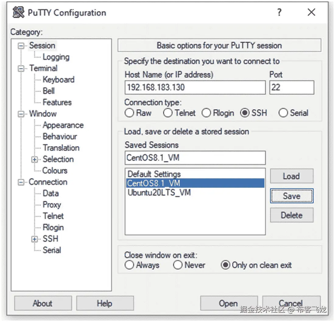图 11-9。PuTTY,为了方便起见保存 Linux 会话 |
| | 如果没有通信问题,您现在可以在 Linux 服务器上编写一些 Python 脚本,并与 Cisco IOS 路由器通信。从你的 Linux 服务器,发送 ICMP 消息到 R1 的`f0/0`界面进行快速验证。`[pynetauto@centos8s1 ~] ping 192.168.183.133 -c 3PING 192.168.183.133 (192.168.183.133) 56(84) bytes of data.64 bytes from 192.168.183.133: icmp_seq=1 ttl=64 time=0.547 ms64 bytes from 192.168.183.133: icmp_seq=2 ttl=64 time=0.318 ms64 bytes from 192.168.183.133: icmp_seq=3 ttl=64 time=0.372 ms--- 192.168.183.133 ping statistics ---3 packets transmitted, 3 received, 0% packet loss, time 44msrtt min/avg/max/mdev = 0.318/0.412/0.547/0.099 mspynetauto@ubuntu20s1:~` `ping 192.168.183.133 -c 3``PING 192.168.183.133 (192.168.183.133) 56(84) bytes of data.``64 bytes from 192.168.183.133: icmp_seq=1 ttl=255 time=5.92 ms``64 bytes from 192.168.183.133: icmp_seq=2 ttl=255 time=6.85 ms``64 bytes from 192.168.183.133: icmp_seq=3 ttl=255 time=5.70 ms``--- 192.168.183.133 ping statistics ---``3 packets transmitted, 3 received, 0% packet loss, time 2004ms``rtt min/avg/max/mdev = 5.699/6.158/6.851/0.498 ms` |
| **11** | 在 R1 上,配置具有 15 级权限的用户名`enable password`,并启用 Telnet。`R1#` `configure terminal``R1(config)#` `enable password cisco123``R1(config)#` `username pynetauto privilege 15 password cisco123``R1(config)#` `line vty 0 15``R1(config-line)#` `login local``R1(config-line)#` `transport input telnet``R1(config-line)#` `no exec-timeout``R1(config-line)#` `end``R1#` `write memory`您可以从路由器本身测试 Telnet 设置,因此在 R1 上,运行`telnet 192.168.183.133`命令。同样,使用`show user`命令来检查登录的用户。`R1#` `telnet 192.168.183.133``Trying 192.168.183.133 ... Open``User Access Verification``Username:` `pynetauto``Password:``R1#` `show user``Line User Host(s) Idle Location``0 con 0 192.168.183.133 00:00:00``* 98 vty 0 pynetauto idle 00:00:00 192.168.183.133``Interface User Mode Idle Peer Address` |
| **12** | 从您的`ubuntu20s1` Linux 服务器,使用 PuTTY 远程登录到 R1 的`f0/0`接口(192.168.183.133)。您分配的 IP 地址可能不同,因此请用您的 IP 地址替换 IP 地址。运行`show user`命令来检查哪些用户已经登录以及用于 Telnet 会话的线路。星号(`*`)表示来自活动连接的访问信息。`pynetauto@ubuntu20s1:~ telnet 192.168.183.133Trying 192.168.183.133...Connected to 192.168.183.133.Escape character is '^]'.User Access VerificationUsername: pynetautoPassword:R1#` `show userLine User Host(s) Idle Location0 con 0 192.168.183.133 00:05:0798 vty 0 pynetauto idle 00:05:07 192.168.183.133* 99 vty 1 pynetauto idle 00:00:00 192.168.183.132Interface User Mode Idle Peer Address请注意,如果您使用 CentOS 远程登录到 R1,那么您可能需要在连接到互联网后首先安装 Telnet 客户端。[pynetauto@centos8s1 ~] sudo dnf -y install telnet | | **13** | 现在,从您的 Windows 主机上,打开另一个 PuTTY 会话,这次通过f0/1 (7.7.7.2)登录到 R1。*表示来自当前连接的访问信息。让我们运行write memory来保存 R1 的当前配置。R1# show userLine User Host(s) Idle Location0 con 0 idle 00:05:4398 vty 0 pynetauto idle 00:00:40 192.168.183.13399 vty 1 pynetauto idle 00:01:10 192.168.183.132*100 vty 2 pynetauto idle 00:00:00 7.7.7.1Interface User Mode Idle Peer Address``R1# write memory` |
现在,您已经完成了所有设备的通信和 Telnet 测试。现在,您已经准备好处理另一个有趣的 IOS 实验室了。
从 Linux 虚拟机向 GNS3 IOS 路由器上传和下载文件(文件传输测试实验室)
在本实验中,您将向 GNS3 的 IOS 路由器 R1 添加闪存,并从 TFTP 服务器(CentOS8.1)上传和下载文件。您将从 Ubuntu 20 LTS 服务器编写并运行该脚本。
编写一个 Python 脚本来完成以下任务:
|#
|
任务
|
| --- | --- |
| 1 | 在 GNS3 上,创建 Cisco 3725 IOS 路由器模板时,您已经向 Cisco 3725 的 PCMCIA disk0 添加了 64MB。If your router was not configured with a flash drive, first save the work and shut down the router. Then right-click, choose Configure, and move to the “Memories and disks” tab of R1. Add 64MB, click Apply, and then click the OK button. Once the flash memory has been configured, start R1 again. See Figure 11-10.图 11-10。R1,检查闪存分配 |
| 2 | 还记得在 8.3.3 中,我们在 CentOS8.1 上配置了一个 TFTP 服务器吗?转到 CentOS8.1 的 PuTTY 会话,现在确认 TFTP 服务的状态。TFTP 是在 CentOS8.1 Linux 上安装 IP 服务时配置的。Use the following commands to check for TFTP services running on CentOS8.1.
如果 CentOS 8.1 上的 TFTP 服务运行正常,它应该以绿色显示活动(正在运行)。如果 TFTP 有问题,请使用前面显示的enable和start命令来启动该服务器上的服务。如果 CentOS 询问sudo用户密码,请输入您的密码。在 4.5.3 中,我们为 TFTP 服务配置了一个名为/var/tftpdir的默认文件夹,以便在该文件夹中共享文件。[pynetauto@localhost ~]$ sudo systemctl enable tftp``[sudo] password for pynetauto: **********``[pynetauto@localhost ~]$ sudo systemctl start tftp``[pynetauto@localhost ~]$ sudo systemctl status tftp``● tftp.service - Tftp Server |
| | Loaded: loaded (/usr/lib/systemd/system/tftp.service; indirect; vendor prese>``Active: active (running) since Fri 2021-01-08 23:43:05 AEDT; 4s ago``Docs: man:in.tftpd``Main PID: 4237 (in.tftpd)``Tasks: 1 (limit: 11166)``Memory: 328.0K``CGroup: /system.slice/tftp.service``└─4237 /usr/sbin/in.tftpd -s /var/lib/tftpboot``Jan 08 23:43:05 localhost systemd[1]: Started Tftp Server.``lines 1-11/11 (END) |
| 3 | 在你的 Ubuntu 服务器(主要 Python 服务器)上,重用第十章中telnet_script1的 Telnet 示例代码,让我们重写 Telnet 脚本来备份 R1 的运行配置。我将把脚本重命名为backup_config.py并修改代码。被修改的代码部分被突出显示。转到 Ubuntu 20 LTS Python 服务器,使用 nano 文本编辑器创建以下代码:pynetauto@ubuntu20s1:~$ pwd``/home/pynetauto``pynetauto@ubuntu20s1:~$ mkdir ch11``pynetauto@ubuntu20s1:~$ cd ch11``pynetauto@ubuntu20s1:~/ch11$ nano backup_config.py``pynetauto@ubuntu20s1:~/ch11$ ls``backup_config.py``backup_config.py``import getpass``import telnetlib``HOST = "192.168.183.133"``user = input(``"Enter your telnet username: "``password = getpass.getpass()``tn = telnetlib.Telnet(HOST)``tn.read_until(b"Username: ")``tn.write(user.encode('ascii') + b"\n")``if password :``tn.read_until(b"Password: ")``tn.write(password.encode('ascii') + b"\n")``tn.write(b"copy running-config tftp://192.168.183.130/running-config\n") #<<< Copy command``tn.write(b"\n") #<<< Enter key action``tn.write(b"\n") #<<< Enter key action``tn.write(b"exit\n") #<<< end session``print(tn.read_all().decode('ascii')) |
| 4 | 在运行前面的脚本之前,转到 CentOS8s1 并确认/var/tftpdir目录中的文件。你可以看到 8.3.3 中只有两个传输测试文件。[pynetauto@centos8s1 ~]$ pwd``/home/pynetauto``[pynetauto@centos8s1 ~]$ cd /var/tftpdir``[pynetauto@centos8s1 tftpdir]$ ls``transfer_file01 transfer_file77 |
| 5 | 现在从 Ubuntu 20 LTS Python 服务器,运行python3 backup_config.py命令。按照提示操作并检查返回的输出。输入您的网络管理员 ID 和密码来运行脚本。当运行配置被复制到 TFTP 服务器时,您应该会看到类似以下内容的消息:pynetauto@ubuntu20s1:~/ch11$ python3 backup_config.py``Enter your telnet username: pynetauto``Password: *********``R1#copy running-config tftp://192.168.183.130/running-config``Address or name of remote host [192.168.183.130]?``Destination filename [running-config]?``!!``1155 bytes copied in 2.168 secs (533 bytes/sec)``R1#exit |
| 6 | 现在回到 CentOS8s1 服务器,重新检查目录(/var/tftpdir)。您现在应该看到running-config文件保存在 TFTP 服务器上。[pynetauto@centos8s1 tftpdir]$ ls``running-config transfer_file01 transfer_file77 |
| 7 | 现在,要将 IOS 映像上传到 GNS3 的 IOS 路由器的闪存,首先必须格式化闪存。打开 R1 的控制台,按照以下说明操作:R1# show flash``No files on device``134211584 bytes available (2198889009152 bytes used)``R1#``*Mar 1 02:53:58.163: %PCMCIAFS-5-DIBERR: PCMCIA disk 0 is formatted from a different router or PC. A format in this router is required before an image can be booted from this device``R1# show file system |
| | File Systems:``Size(b) Free(b) Type Flags Prefixes``- - opaque rw archive:``- - opaque rw system:``- - opaque rw tmpsys:``57336 54057 nvram rw nvram:``- - opaque rw null:``- - network rw tftp:``* 2199023220736 134211584 disk rw flash:``- - flash rw slot0:``- - opaque wo syslog:``- - opaque rw xmodem:``- - opaque rw ymodem:``- - network rw rcp:``- - network rw pram:``- - network rw ftp:``- - network rw http:``- - network rw scp:``- - opaque ro tar:``- - network rw https:``- - opaque ro cns:``R1#``format flash``Format operation may take a while. Continue? [``confirm``Format operation will destroy all data in "flash:". Continue? [``confirm``Writing Monlib sectors....``Monlib write complete``Format: All system sectors written. OK...``Format: Total sectors in formatted partition: 131040``Format: Total bytes in formatted partition: 67092480``Format: Operation completed successfully.``Format of flash: complete``R1#``show flash``No files on device``66936832 bytes available (0 bytes used) |
| 8 | 您可以使用 Windows 或 WinSCP 的 FileZilla 客户端上传任何 IOS 文件或任何使用 Python telnetlib模块进行文件传输的文件。如果您的 Windows 主机 PC 上没有 WinSCP,请转到以下下载站点并安装一个:URL:https://winscp.net/eng/download.php(wincp 下载)网址:https://filezilla-project.org/download.php?platform=win64(Windows 版 FileZilla 客户端)安装 WinSCP 并启动应用后,使用以下设置通过端口 22 (SSH)连接到 CentOS8.1 服务器。参见图 11-11 。文件协议: SCP主机名: **192.168.183.130(您的 CentOS 8.1 IP 地址)**用户名: **pynetauto(您的 CentOS 8.1 用户名)**密码: **********(你的 CentOS 8.1 密码) |
| | 图 11-11。WinSCP,连接到 TFTP 服务器(CentOS8.1) |
| 9 | When you accept the SSH key and log in, drill down to the
/var/tftpdir/ directory of your TFTP (CentOS8.1) server and drag and drop an IOS file for file sharing. You can also use another file in place of the IOS file to save time as you will be testing the file transfer concept only using Python’s telnetlib module. In this example, I am using the old IOS file named c3725-adventerprisek9-mz.124-15.T14.bin, but you can choose to use any file here for this test. See Figure 11-12.图 11-12。WinSCP,复制 IOS 或任何文件传输测试文件 |
| 10 | 在 R1 上,闪存驱动器已经在前面的步骤中格式化,没有必要检查闪存上是否存在任何文件。 |
| 11 | 现在在 Ubuntu 20 LTS 服务器上,复制
backup_config.py并保存为upload_ios.py。pynetauto@ubuntu20s1:~/ch11$ ls``backup_config.py``pynetauto@ubuntu20s1:~/ch11$ cp backup_config.py upload_ios.py``pynetauto@ubuntu20s1:~/ch11$ nano upload_ios.py然后修改 Python 代码,使其看起来像下面的代码。更新后的零件会突出显示。您可以从头开始输入脚本,但是重用之前的脚本并进行必要的修改会更容易。此外,可以从官方下载站点下载该脚本。 |
| | upload_ios.py``import getpass``import telnetlib``HOST = "192.168.183.133"``user = input(``"Enter your telnet username: "``password = getpass.getpass()``tn = telnetlib.Telnet(HOST)``tn.read_until(b``"Username: "``tn.write(user.encode('ascii') + b"\n")``if password :``tn.read_until(b"Password: ")``tn.write(password.encode('ascii') + b"\n")``tn.write``(``b"``tn.write(b”\n”) #<<< Enter key action``tn.write(b”exit\n”) #<<< end session``print(tn.read_all().decode('ascii')) |
| 12 | 运行 Python 代码。看起来应用挂起了,但实际上,它正在将文件从 TFTP 服务器传输到 R1 的闪存中。TFTP 是一种慢速协议,传输这个 45MB 的文件需要很长时间。在您的实践中,您可以创建任何较小的虚拟.txt文件以节省时间。pynetauto@ubuntu20s1:~/ch11$ python3 upload_ios.py``Enter your telnet username: pynetauto``Password: ********| |
| 13 | 运行前面的脚本后,返回 R1 的控制台,使用show users命令进行远程登录的 vty 会话,并使用dir或show flash:命令检查文件传输是否正在进行。R1#``show flash``-#- --length-- -----date/time------ path``1 1470464 Mar 01 2002 01:02:28 c3725-adventerprisek9-mz.124-15.T14.bin``65466368 bytes available (1470464 bytes used)``R1#``show flash``-#- --length-- -----date/time------ path``1 2936832 Mar 01 2002 01:02:58 c3725-adventerprisek9-mz.124-15.T14.bin``64000000 bytes available (2936832 bytes used) |
| 14 | 如果您正在上传一个 IOS 文件,如本例所示,通过 TFTP 完成文件传输需要一段时间。TFTP 协议使用 UDP 端口进行文件传输,但在实验室和生产环境中都是一种慢速文件传输协议。您只需上传一个文件来学习使用 Python 3 脚本进行 TFTP 文件传输的概念。您无法更新启动系统配置,也无法使用新的 IOS 映像重新启动 GNS3 IOS 路由器;这是在 GNS3 上使用 IOS 的缺点之一。但是,在 VMware Workstation 上使用 Cisco CSR1000v 或 Nexus 9000v,可以模拟实际的 IOS XE 升级过程,包括引导到新升级的 IOS。在下一章中,我们将在 VMware Workstation 上使用 Cisco CSR1000v 并模拟完整的 IOS 升级过程。一旦文件大小达到预期的文件大小,您就知道脚本和文件传输已经成功完成。R1# dir``Directory of flash:/``1 -rw- 46380064 Mar 1 2002 01:22:04 +00:00 c3725-adventerprisek9-mz.124-15.T14.bin``66936832 bytes total (20553728 bytes free)``R1#``show flash``-#- --length-- -----date/time------ path``1 46380064 Mar 01 2002 01:22:04 c3725-adventerprisek9-mz.124-15.T14.bin``20553728 bytes available (46383104 bytes used) |
| 15 | 由于缓慢的上传时间和 Python 的telnetlib库的问题,你的 Ubuntu Python 服务器控制台可能仍然看起来像是在上传 IOS。按 Ctrl+Z 退出此状态以完成本实验。pynetauto@ubuntu20s1:~/ch11$ python3 upload_ios.py``Enter your telnet username: pynetauto``Password:``^Z``[1]+ Stopped python3 upload_ios.py``pynetauto@ubuntu20s1:~/ch11$ |
-
检查 CentOS8.1 上的 TFTP 服务是否正常运行
-
将 R1 的运行配置备份到 TFTP 服务器。
-
上传一个 IOS 到 R1 的闪存进行快速测试。
你已经使用远程登录和 TFTP 服务上传文件到 R1 的闪存。网络工程师的大部分工作涉及 IOS 补丁管理,包括将 IOS 上传到许多路由器和交换机。想象一下,你正在编写一段代码,这段代码可以在晚上你安然入睡时将多个 IOS 文件上传到数百台思科路由器和交换机。实际上,这是我为定期修补客户网络设备而创建的首批工具之一。
复制(克隆)GNS3 项目
为了准备下一章,让我们复制和克隆当前项目。大约有三种不同的方法可以制作 GNS3 项目的副本。第一种方法是使用 GNS3 菜单的“将项目另存为…”功能,第二种方法是将其导出为可移植项目并在另一台主机上重新导入,最后一种方法是使用“导出配置”方法导出您设备的配置并手动克隆您的 GNS3 项目。这些方法是按照难度增加的顺序提到的。另外,请注意,如果您使用第一种方法,您现有的实验室配置将被移动到新保存的Project文件夹中。您将丢失设备运行配置的现有配置。克隆 GNS3 项目的最佳方式是使用第三种方法,它保留您现有的实验室状态,并将相同的设置带到新项目中。最后,但也是最重要的,如果你想在任何时候对你的 GNS3 项目做一个完整的备份,你可以在C:\Users\[your_name]\GNS3\project下复制整个项目文件夹。
因为在本书的这一点之外我们不会使用linuxvm2ios项目,所以让我们看看如何使用复制方法克隆 GNS3 项目。在后面的章节中,将演示另一种方法,为您提供另一个克隆选项。
#
|
任务
|
| --- | --- |
| 1 | Make sure all devices in the GNS3 project are powered off. To save the existing linuxvm2ios project to a new project name, first open GNS3’s main user window, go to File, and select “Save project as.” See Figure 11-13.图 11-13。GNS3,“项目为…”菜单 |
| 2 | GNS3 项目保存在
C:\Users\[your_name]\GNS3\project文件夹下。现在,给你的第十二章的新项目起一个新名字。本实验将在后续实验中使用。参见图 11-14 。GNS3 project folder location: C:\Users\brendan\GNS3\projects图 11-14。GNS3,将现有的 linuxvm2ios 项目克隆到 cmllab-basic |
| 3 | After you saved the new project, go to the
Project folder (C:\Users\[your_name]\GNS3\projects) and check the original and new project folders’ file sizes. The original project folder size will be around 24KB in size, whereas the new project folder size will be over 2.1MB. Open the folder and check the folder and file contents. See Figure 11-15.图 11-15。主机,确认新的项目文件夹 |
| 4 | Now open the new project and run it. If you have saved the project correctly, it should run smoothly with no errors. Now you are ready for some CML-PE labs in Chapter 12. See Figure 11-16.
图 11-16。GNS3,运行 cmllab-basic 项目 |
摘要
在本章中,您通过 Telnet 测试了 Linux 虚拟机与 IOS 路由器 R1 的交互。您学习了如何创建 GNS3 项目,使用简单的 Cisco 配置运行了一个快速文件传输测试实验室,最后学习了如何克隆 GNS3 项目。你现在已经做好准备,可以处理第 12 到 18 章中的其他实验。在第十二章中,我们将使用从前面章节中获得的许多技能,使用集成到 GNS3 中的 Cisco CML (VIRL)镜像来构建 L3 路由和 L2 交换实验室。我们将在第十三章中使用telnetlib模块,向 Python 网络自动化迈出一小步,然后在第十四章中学习使用 SSH 协议控制思科 VIRL 设备。Python 脚本将在 Linux 虚拟机上运行,使用telnetlib、paramiko和netmiko库通过 Telnet 和 SSH 协议控制思科 VIRL 设备。
十二、构建 Python 自动化实验室环境
到目前为止,我们一直在 Telnet 实验室中测试运行过时 IOS 版本(12.x)的旧 Cisco 设备。为了在较新的 IOS 版本上测试新功能,并为我们的实验室配备交换(L2)功能,我们需要将 Cisco CML-PE 的 L2 和 L3 映像集成到 GNS3 实验室环境中。本章将指导您在 GNS3 上完成思科 CML-PE L2 和 L3 映像集成。将指导您完成在 GNS3 环境中下载和集成 L2 和 L3 映像的每个步骤,以便您可以在下一章的网络实验室中使用更新的 IOS 功能集进行测试。您将了解 CML-PE 产品,下载实验室所需的图像,在 GNS3 上集成下载的图像,然后构建 CML-PE 基本实验室拓扑,以测试以下章节中的各种 Python 网络实验室。
在本书中,你已经在你的第一次网络自动化之旅中走了很长的路。到目前为止,我希望您没有失去学习 Python 网络自动化的热情。为了从本书的后半部分获得最大收益,本书假设你已经彻底阅读了前 11 章。在 Python 网络自动化旅程的前半部分,您已经掌握了使用大量开源和专有软件安装、运行和配置集成虚拟实验室所需的各种基本实践技能。您还开始使用目前所学的知识编写基本的 Python 脚本。当然,我们还可以讨论更多令人兴奋的话题,比如 DevOps 概念、Ansible、ACI、REST API、HTML、Postman、YANG、NETCONF 等等。然而,这本书的目的是明确的:我们一直关注让你开始 Python 编程的本质任务,这是所有 Python 应用开发工程师的基本技能。你可能听过这样一句话“给一个人一条鱼,你喂他一天;教一个人钓鱼,你喂他一辈子。”借用 Python 网络应用开发的这个伟大成语,“教一个网络工程师如何使用 Ansible,你让他成为一个驱动;教他怎么用 Python 写代码,你就把他变成一辈子机械师。”因此,扩展你从阅读本书中获得的技能是你的责任;只有你能决定你下一步要去哪里,以及如何将新技能应用到你的工作或学习中。
到目前为止,您已经学习了各种 IT 技能,为接下来主要关注 Python 网络自动化实验室的章节做好了准备。如果您到目前为止没有遇到任何技术问题,那么您应该能够轻松地阅读剩余的章节。如果您还没有完全设置好您的实验环境,或者如果您只完成了每章中的部分练习,我建议您回去完成,因为您将需要所有这些基础知识。
在本章中,我们将从第十一章结束时停止的地方开始,完成构建的基本 CML lab-基本实验室拓扑,以开始编写 Python 代码并测试用于网络自动化应用开发的代码。假设您是一名经验丰富的网络工程师,拥有多年使用 Cisco、Juniper、Arista 和 HP 网络设备的经验。在这种情况下,您在学习本实验的内容时不会有任何问题。然而,即使您是一名刚刚开始职业生涯的网络工程师,您仍然能够按照所有实验步骤进行操作,因为这些实验只包含最基本的网络概念,并附有足够的培训说明。如果你集中注意力,你将能够毫不费力地完成所有的实验。
思科 CML-个人软件许可信息和软件下载
思科出售思科建模实验室-个人(CML-个人)与年度订阅。如果您是一名网络工程师或网络专业的学生,想要探索 Cisco CML-PERSONAL 所提供的一切,购买订阅是一个不错的选择。在订阅的第一年,您需要支付 199 美元,并且您将继续支付思科学习团队指定的相同的年度订阅费。对于一个以思科技术为生的专业工程师来说,与传统网络工程师为了进入这个行业而不得不花费在他们的旧的 3700 和 2600 系列路由器和 2950 系列交换机上的费用相比,订阅费是便宜的。无论如何,如果你能得到 CML 图像,有更具成本效益的方法来建立你的实验室,比如将它们集成到 GNS3 中,这是本章的主题。
正如在第一章中提到的,CML-PERSONAL(改名为 VIRL-PE,虚拟互联网路由实验室个人版)是一个虚拟设备仿真器程序,用于研究思科的技术,所以你可以说它是特定于供应商的。然而,您将从思科工具中学到的网络概念将是通用的,并可复制到其他供应商的技术中。一旦您订阅了 Cisco CML-PERSONAL,您就可以下载并安装 Cisco 的 CML-PERSONAL 软件,并使用路由器、交换机和防火墙 CML-PERSONAL 映像来模拟各种 Cisco 实验室。不出所料,本书没有使用 CML-PERSONAL PE,而是使用混合实验室设置,在 GNS3 上使用 Cisco CML-PERSONAL 的路由器(L3)和交换机(L2)映像。GNS3 上的 CML-个人映像安装和集成程序与 GNS3 上的 Cisco 路由器 IOS 映像集成几乎相同。同样,您的 Windows 主机需要连接到互联网。CML-PERSONAL 是思科的专有软件,法律禁止免费分发 CML-PERSONAL 软件和 CML-PERSONAL 图像。如果您有能力订阅,我们推荐您在 https://learningnetworkstore.cisco.com/cisco-modeling-labs-personal/cisco-cml-personal 订阅 CML-PERSONAL。
本书声明任何 Cisco IOS、CML-PERSONAL 或任何其他专有软件的购买和使用都是您的责任。本书不包含任何软件。有几种方法可以找到本书中提到的软件。更多信息请参考 https://developer.cisco.com/modeling-labs/ 。
下载 Cisco CML-个人 IOSvL2(交换机)镜像
在我们将 Cisco CML-PERSONAL L2 交换机映像集成到 GNS3 之前,您需要找到、下载并保存到您的主机 PC 的Downloads文件夹中。您可以从 GNS3 官方网站获得有关 CML-PERSONAL L2 交换机的信息,该网站将带您到思科的 CML-PERSONAL L2 网站( https://learningnetwork.cisco.com/s/article/iosvl2-more-info-updated-10-2-15-x )。
本书使用的 CML-PERSONAL switch 镜像名称为vios_l2-adventerprisek9-m.03.2017.qcow2。您可以使用同一个或您可以找到并下载的任何更新的图像。下载交换机镜像文件后,保存到Downloads文件夹。将其保存到Downloads文件夹对于节省时间很重要,因为 GNS3 将首先在Downloads文件夹中查找图像(参见图 12-1 )。
图 12-1。
CML-个人 L2 交换机图像,保存到下载文件夹
下载 Cisco CML-PERSONAL IOSv(路由器)镜像和启动配置文件
要集成 CML-PERSONAL L3 或路由器映像,您必须下载工作 IOSv L3 Qemu ( qcow2)和IOSv_startup_config.img映像文件。与 L2 交换机不同,CML-PERSONAL 路由器镜像与 GNS3 的集成也需要用于设备启动的IOSv_startup_config.img文件,该文件可以从 CML-PERSONAL 的官方网站下载,或者关于 GNS3 CML-PERSONAL L3 路由器和IOSv_startup_config.img的sourceforge.net.信息可以从思科的 CML-PERSONAL 网站获得。请访问以下推荐网站,了解有关 Cisco CML-PERSONAL L3 软件的更多信息:
-
GNS 3 CML-个人 IOSv :
https://learningnetwork.cisco.com/s/article/iosv-more-info-updated-4-20-15-x -
CML-个人 IOSv_startup_config 文件下载 :
https://sourceforge.net/projects/gns-3/files/Qemu%20Appliances/
本书使用的 CML-PERSONAL IOSv 或 L3 路由器镜像名为IOSv-L3-15.6(2)T.qcow2;这是一个旧的图像,但它仍然符合我们的需要。由于我们没有探索所有的网络功能,思科设备仅满足我们学习网络自动化概念和 Python 应用开发的需要。我们可以使用任何版本的 CML L2 和 L3 映像,只要它能够承载流量,并节省我们运行成熟的基于硬件的实验室所需的时间和资源。尽管我们关注的是网络自动化,但路由和交换概念并不是本书的核心。因此,Cisco CML-PERSONAL images 为我们提供了基本的 L2 和 L3 连接来承载流量,并使用 Telnet、SSH、RESTCONF 和其他 Python 库来学习 Python 脚本编写技能。下载两个需要的文件,如图 12-2 所示,保存在Downloads文件夹中。
图 12-2。
CML-个人 L3 路由器映像,保存在下载文件夹中
一旦有了 vIOS L2 映像、vIOS L3 映像和 vIOS 启动配置文件,就可以将它们安装并集成到 GNS3 中了。
在 GNS3 上安装思科 CML-个人 L2 交换机和 CML-个人 L3
在第十一章的结尾,我们复制并创建了一个名为cmllab-basic的新项目。让我们重新打开那个项目,因为这是我们本章任务的起点。如果您从第十一章继续工作,请从 GNS3 继续工作,但是如果您刚刚打开 PC,那么首先使用桌面上的 GNS3 快捷图标启动 GNG3。如果实验环境设置正确,GNS3 将运行,安装在 VMware Workstation 上的 GNS3 虚拟机将在几秒钟后自动启动。
Installation tip
如果由于软件故障导致 CML-PERSONAL 安装无法正常工作,您必须通过右键单击 GNS3 删除已安装的交换机或路由器模板,并尝试再次安装映像。CML-个人图像不是为 GNS3 制作的,所以有时它们在第一次尝试时不会集成到 GNS3。如果 CML-PERSONAL 映像在第一次尝试后没有正确安装,不要放弃;继续尝试,直到它被正确安装。
在 GNS3 上安装思科 CML-个人 L2 交换机
您将首先在 GNS3 上安装思科 CML-个人 L2 交换机镜像。为了正确安装,主机必须连接到互联网。安装完成后,您将使用安装的映像运行交换实验,这在早期的 IOS 映像集成中是不可能的。
||
工作
|
| --- | --- |
| 1 | In the GNS3 main window, go to File and click + New template . See Figure 12-3.图 12-3。CML L2 交换机安装,添加新模板 |
| 2 | When the “New template” wizard opens , leave the default selection of “Install an appliance from the GNS3 server (recommended)” and click Next. See Figure 12-4.
图 12-4。CML L2 交换机安装,新模板选择 |
| 3 | In the “Appliances from server**”** window , in the search field, type in IOSvL2 to locate Cisco IOSvL2 Qemu under Switches. Select the searched device and click Install; this is the template for the Cisco CML-PERSONAL L2 switch on GNS3. See Figure 12-5.
图 12-5。CML L2 交换机安装,来自服务器的设备 |
| 4 | In the Server window , click Next. See Figure 12-6.
图 12-6。CML L2 交换机安装,服务器 |
| 5 | In the “Qemu settings” window , click Next. See Figure 12-7.
图 12-7。CML L2 交换机安装,Qemu 设置 |
| 6 | Under “Required files,” if you have placed the CML-PERSONAL L2
.qcow2 file in the Downloads folder, the installation wizard will automatically detect the L2 image automatically and display it in green. You can also see the missing files in red. Highlight your image and click Next. See Figure 12-8.图 12-8。CML L2 交换机安装,所需文件 |
| 7 | When the Appliance window pops up , click Yes. See Figure 12-9.
图 12-9。CML L2 安装,设备安装弹出窗口 |
| 8 | To complete the installation , click Finish. See Figure 12-10.
图 12-10。CM L2 开关的安装、使用 |
| 9 | The “Add template” window pops up ; click OK to finish the installation. See Figure 12-11.
图 12-11。CML L2 交换机安装,弹出“添加模板” |
| 10 | On GNS3, click the Switch button on the left, which looks like two opposite arrows, to open the switches. See Figure 12-12.
图 12-12。CML L2 交换机安装,选择 GNS3 上的交换机图标 |
| 11 | If Cisco CML-PERSONAL IOSvL2 was installed correctly, you would see your new switch devices installed under Switches. See Figure 12-13.
图 12-13。CML L2 交换机安装,选择 Cisco IOSvL2 交换机 |
| 12 | Now, drag and drop the IOSvL2 switch to the cmllab-basic lab, as shown in Figure 12-14.
图 12-14。CML L2 交换机安装,拖放 CML 交换机 |
| 13 | Using the Add Link tool, connect Gi0/0 of the new switch to Switch1’s e2 interface, as shown in Figure 12-15. Then power on all devices on the topology and also the CentOS8.1 and Ubuntu 20.04 LTS servers on VMware Workstation 15 Pro. Rename the switch to LAB-SW1 by right-clicking and clicking the Change Hostname menu.
图 12-15。CML L2 交换机安装,将 CML 交换机连接到网络 |
| 14 | After powering on LAB-SW1, open its console, and you will see a similar power-on screen as shown in Figure 12-16.
图 12-16。CML L2 交换机安装,通电 CML 交换机屏幕 |
| 15 | 如果新交换机成功启动,它的控制台屏幕应该如下所示。现在,您已经在 GNS3 上完成了 CML 个人 L2 交换机的安装。为一些交换实验室做好准备。 |
| |
Cisco IOS Software, vios_l2 Software (vios_l2-ADVENTERPRISEK9-M), Experimental Version 15.2(20170321:233949) [mmen 101] |
| | Copyright (c) 1986-2017 by Cisco Systems, Inc. |
| | Compiled Wed 22-Mar-17 08:38 by mmen |
| | ************************************************************************** |
| | * IOSv is strictly limited to use for evaluation, demonstration and IOS * |
| | * education. IOSv is provided as-is and is not supported by Cisco's * |
| | * Technical Advisory Center. Any use or disclosure, in whole or in part, * |
| | * of the IOSv Software or Documentation to any third party for any * |
| | * |
| | *Jan 9 10:36:48.512: %PLATFORM-5-SIGNATURE_VERIFIED: Image 'flash0:/vios_l2-adventerprisek9-m' passed code signing verification purposes is expressly prohibited except as otherwise authorized by * |
| | * Cisco in writing. * |
| | ************************************************************************** |
| | Switch> |
GNS3 上 CML L2 交换机集成的快速通信测试
在 CML-PERSONAL L2 交换机安装结束时,快速执行从交换机到网络上其它设备的通信检验。推荐的 ICMP 测试描述如下:
||
工作
|
| --- | --- |
| 1 | 快速登录并使用有效的 IP 地址在新交换机上配置正确的交换机名称和 VLAN 1 接口。 |
| | Switch>``enable |
| | Switch#``configure terminal |
| | LAB-SW1(config)#``hostname LAB-SW1 |
| | LAB-SW1(config)#``spanning-tree vlan 1 root primary |
| | LAB-SW1(config)#``interface vlan 1 |
| | LAB-SW1(config-if)#``ip add 192.168.183.101 255.255.255.0 |
| | LAB-SW1(config-if)#``no shut |
| | LAB-SW1(config-if)#``end |
| 2 | 在 LAB-SW1 上,当您打开 Gi0/0 时,R1 的 f0/0 接口可能会提示您双工不匹配错误。要在 LAB-SW1 上停止这条恼人的 CDP 错误消息,您需要将 R1 的 f0/0 接口速度硬编码为 100,并将双工编码为全双工。如果没有出现此错误,您可以继续下一步。 |
| | LAB-SW1(config-if)# |
| | *Aug 2 11:16:38.977: %CDP-4-DUPLEX_MISMATCH: duplex mismatch discovered on GigabitEthernet0/0 (not half duplex), with R1 FastEthernet0/0 (half duplex). |
| | 打开 R1 控制台,按如下方式更改接口速度和双工: |
| | R1#``configure terminal |
| | R1(config)#``interface f0/0 |
| | R1(config-if)#``duplex full |
| | R1(config-if)#``speed 100 |
| | R1(config-if)#``do write memory |
| 3 | 转到 PC1,运行ip dhcp命令获取 IP 地址,或者如果您继续上一章的实验,运行show ip命令检查 PC1 的 IP 地址。 |
| | PC1>``ip dhcp |
| | DDORA IP 192.168.183.129/24 GW 192.168.183.2 |
| | PC1>``show ip |
| | NAME : PC1[1] |
| | IP/MASK : 192.168.183.129/24 |
| | GATEWAY : 192.168.183.2 |
| | DNS : 192.168.183.2 |
| | DHCP SERVER : 192.168.183.254 |
| | DHCP LEASE : 1713, 1800/900/1575 |
| | DOMAIN NAME : localdomain |
| | MAC : 00:50:79:66:68:00 |
| | LPORT : 20012 |
| | RHOST:PORT : 127.0.0.1:20013 |
| | MTU: : 1500 |
| 4 | 从实验室-SW1 (192.168.183.101)向 PC1 (192.168.183.129)和 R1 的 f0/0 (192.168.183.133)发送 ICMP 消息。 |
| | LAB-SW1# ping 192.168.183.129 |
| | Type escape sequence to abort. |
| | Sending 5, 100-byte ICMP Echos to 192.168.183.129, timeout is 2 seconds: |
| | .!!!! |
| | Success rate is 100 percent (5/5), round-trip min/avg/max = 2/3/5 ms |
| | LAB-SW1# ping 192.168.183.133 |
| | Type escape sequence to abort . |
| | Sending 5, 100-byte ICMP Echos to 192.168.183.133, timeout is 2 seconds: |
| | .!!!! |
| | Success rate is 80 percent (4/5), round-trip min/avg/max = 2/4/6 ms |
| 5 | 确保两台 Linux 服务器都已启动并在 VMware Workstation 上运行。从上一章我们知道centos8s1服务器的 IP 地址是 192.168.183.130,ubuntu20s1服务器的 IP 地址是 192.168.183.132。 |
| | 从 LAB-SW1 向centos8s1和ubuntu20s1发送 ICMP 数据包(ping)。您的服务器 IP 地址可能与此处显示的示例不同: |
| | LAB-SW1# ping 192.168.183.130 |
| | Type escape sequence to abort. |
| | Sending 5, 100-byte ICMP Echos to 192.168.183.130, timeout is 2 seconds: |
| | !!!!! |
| | Success rate is 100 percent (5/5), round-trip min/avg/max = 3/6/13 ms |
| | LAB-SW1# ping 192.168.183.132 |
| | Type escape sequence to abort . |
| | Sending 5, 100-byte ICMP Echos to 192.168.183.132, timeout is 2 seconds: |
| | !!!!! |
| | Success rate is 100 percent (5/5), round-trip min/avg/max = 2/3/6 ms |
| 6 | 通信测试成功后,将运行配置复制到启动配置。 |
| | LAB-SW1#``copy running-config startup-config |
| | Destination filename [startup-config]? |
| | Building configuration... |
| | Compressed configuration from 3559 bytes to 1604 bytes[OK] |
现在,您已经在 GNS2 上完成了 CML L2 交换机映像的集成和验证。有了这个图像,我们可以用许多交换机来测试多设备 Python 网络自动化实验室。接下来,继续集成 L3 路由器映像。
在 GNS3 上安装 Cisco CML-PERSONAL L3 路由器
现在,您将按照本节所示的步骤在 GNS3 上安装 CML-PERSONAL L3 路由器;这将使您能够在 GNS3 上运行 CML 个人路由器。和往常一样,您需要连接到互联网才能完成此过程。最好是连接到家庭网络,而不是在安装过程中工作。请注意,如果您的主机通过公司代理连接到互联网,您可能会遇到一些问题。参见图 12-17 。
图 12-17。
GNS3,CML-个人 L3 图像错误
CML 图像的集成看起来很正常,直到您将图标拖放到 GNS3 拓扑画布上。如果 GNS3 产生一个qcow2或其他错误并且不工作,您可能需要使用如图 12-18 所示的“删除模板”选项,并从头开始整合过程。
图 12-18。
GNS3,删除 CML-个人 L3 模板
现在,为 CML L3 路由器映像添加一个新模板,并完成集成。
||
工作
|
| --- | --- |
| 1 | In the GNS3 main window , go to File and click “+ New template.” See Figure 12-19.图 12-19。CML L3 路由器安装,添加新模板 |
| 2 | When the “New template ” wizard opens, leave the default selection of “Install an appliance from the GNS3 server (recommended)” and click Next. See Figure 12-20.
图 12-20。CML L3 路由器安装,新模板 |
| 3 | In the “Appliances from server ” window, type IOSv in the search field to locate Cisco IOSv Qemu under Switches. Select the searched device and click Install. This is the template for the Cisco CML-PERSONAL L3 router on GNS3. See Figure 12-21.
图 12-21。CML L3 路由器安装,来自服务器的设备 |
| 4 | In the next window , click Next. See Figure 12-22.
图 12-22。CML L3 路由器安装,服务器选择 |
| 5 | On the “Qemu settings” screen , click Next again. See Figure 12-23.
图 12-23。CML L3 路由器安装,Qemu 设置 |
| 6 | It is recommended that you click the actual vIOS name under “Required files” and highlight it before clicking Next. Notice that the actual image name
vios-adventerprisek9-m.vmdk.SPA.156-2.T is selected before clicking the Next button . See Figure 12-24.图 12-24。CML L3 路由器安装,所需文件 |
| 7 | When the Appliance window pops up , click Yes. See Figure 12-25.
图 12-25。CML L3 路由器安装,设备安装弹出窗口 |
| 8 | In the Usage window , click Finish. See Figure 12-26.
图 12-26。CML L3 路由器的安装、使用 |
| 9 | When the “Add template ” message appears, click OK to complete the CML-PERSONAL L3 router image installation. See Figure 12-27.
图 12-27。CML L3 路由器安装,弹出“添加模板” |
| 10 | Go back to the main user window , and this time click the Router icon that looks like a circle with four arrows. See Figure 12-28.
图 12-28。CML L3 路由器安装,单击 GNS3 上的路由器图标 |
| 11 | The Routers list appears as shown in Figure 12-29, and you will immediately notice that a new IOSv router has been added.
图 12-29。CML L3 路由器安装,选择 CML 路由器 |
| 12 | Now drag and drop the new router onto the Topology canvas of the
cmllab-basic project. Rename the router as LAB-R1. See Figure 12-30.图 12-30。CML L3 路由器安装,拖放 CML 路由器 |
| 13 | 重命名新路由器后,使用添加链路(连接器)工具,将 R1 实验室的 Gi0/0 接口连接到实验室 SW1 的 Gi0/1 接口。您可以在另一台设备打开时建立连接。现在打开 R1 实验室的电源,打开控制台窗口。见图 12-31 。 |
| | The Topology Summary window shows the virtual connection between devices (see Figure 12-32).The Servers Summary window shows where each device is hosted (see Figure 12-33).
图 12-31。CML L3 路由器安装、连接和启动 CML 路由器
图 12-32。拓扑摘要窗口
图 12-33。服务器摘要窗口 |
| 14 | When the router boots up, it will display the vIOS version during the bootup. See Figure 12-34.
图 12-34。CML L3 路由器安装,开机 CML 路由器屏幕 |
| 15 | 如果您看到类似图 12-35 的控制台屏幕,这意味着您已经在 GNS3 上完成了 CML-PERSONAL L3 路由器。CML-PERSONAL 与 Cisco IOS 15.x 几乎完全相同。现在,您可以使用较新的 IOS 映像进行一些路由实验了。 |
| |
Cisco IOS Software, IOSv Software (VIOS-ADVENTERPRISEK9-M), Version 15.6(2)T, RELEASE SOFTWARE (fc2) |
| | Technical Support: http://www.cisco.com/techsupport |
| | Copyright (c) 1986-2016 by Cisco Systems, Inc. |
| | Compiled Tue 22-Mar-16 16:19 by prod_rel_team |
| | *Jan 9 11:12:35.500: %CRYPTO-6-ISAKMP_ON_OFF: ISAKMP is OFF |
| | *Jan 9 11:12:35.501: %CRYPTO-6-GDOI_ON_OFF: GDOI is OFF |
| | *Jan 9 11:12:37.708: %SYS-3-CPUHOG: Task is running for (1999)msecs, more than (2000)msecs (0/0),process = Crypto CA. |
| | ************************************************************************** |
| | * IOSv is strictly limited to use for evaluation, demonstration and IOS * |
| | * education. IOSv is provided as-is and is not supported by Cisco's * |
| | * Technical Advisory Center. Any use or disclosure, in whole or in part, * |
| | * of the IOSv Software or Documentation to any third party for any * |
| | * purposes is expressly prohibited except as otherwise authorized by * |
| | * Cisco in writing . * |
| | ************************************************************************** |
| | Router# |
GNS3 上集成 CML L3 路由器的快速通信测试
完成以下任务,让新安装的路由器能够与拓扑中的其余设备通信:
||
工作
|
| --- | --- |
| 1 | 快速登录新路由器并配置正确的路由器名称。此外,从与 VMnet8 (192.168.183.0/24)相同的子网配置一个有效的 IP 地址,以便与 gibbit Ethernet 0/0 接口。请注意,您的子网可能不同。确保发出no shut命令调出界面。 |
| | Router#``configure termina |
| | Router(config)#``hostname |
| | LAB-R1(config)#``interface GigabitEthernet 0/0 |
| | LAB-R1(config-if)#``ip add 192.168.183.10 255.255.255.0 |
| | LAB-R1(config-if)#``no shut |
| | LAB-R1(config-if)#``end |
| 2 | 在 R1 实验室路由器上,一旦 Gi0/0 接口出现,就开始向以下 IP 地址发送 ICMP 数据包,以确保 R1 实验室能够与拓扑中的所有其它设备通信。VMnet8 的默认网关 IP (192.168.183.2)、PC1 的 IP 地址(192.168.183.129)、R1 的 f0/0 (192.168.183.133)、centos8s1服务器(192.168.183.130)和ubuntu20s1服务器(192.168.183.132)。 |
| | LAB-R1#``ping 192.168.183.2 |
| | Type escape sequence to abort. |
| | Sending 5, 100-byte ICMP Echos to 192.168.183.2, timeout is 2 seconds: |
| | .!!!! |
| | Success rate is 80 percent (4/5), round-trip min/avg/max = 8/10/11 ms |
| | LAB-R1#``ping 192.168.183.129 |
| | Type escape sequence to abort. |
| | Sending 5, 100-byte ICMP Echos to 192.168.183.129, timeout is 2 seconds: |
| | .!!!! |
| | Success rate is 80 percent (4/5), round-trip min/avg/max = 7/9/12 ms |
| | LAB-R1#``ping 192.168.183.133 |
| | Type escape sequence to abort. |
| | Sending 5, 100-byte ICMP Echos to 192.168.183.133, timeout is 2 seconds: |
| | .!!!! |
| | Success rate is 80 percent (4/5), round-trip min/avg/max = 12/15/18 ms |
| | LAB-R1#``ping 192.168.183.130 |
| | Type escape sequence to abort. |
| | Sending 5, 100-byte ICMP Echos to 192.168.183.130, timeout is 2 seconds: |
| | .!!!! |
| | Success rate is 80 percent (4/5), round-trip min/avg/max = 8/8/11 ms |
| | LAB-R1#``ping 192.168.183.132 |
| | Type escape sequence to abort. |
| | Sending 5, 100-byte ICMP Echos to 192.168.183.132, timeout is 2 seconds: |
| | .!!!! |
| | Success rate is 80 percent (4/5), round-trip min/avg/max = 8/9/10 ms |
| 3 | 仅出于验证目的,我们还可以使用ssh –l username server_IP命令快速测试从 R1 实验室登录 CentOS8.1 服务器的 SSH 登录。 |
| | LAB-R1#``ssh -l pynetauto 192.168.183.130 |
| | Password: |
| | Activate the web console with: systemctl enable --now cockpit.socket |
| | Last login: Sat Jan 9 00:00:39 2021 from 192.168.183.1 |
| | [pynetauto@centos8s1 ~]$ exit |
| | logout |
| | [Connection to 192.168.183.130 closed by foreign host] |
| | LAB-R1# |
| | 请注意,由于安全算法不匹配,SSH 无法登录到ubuntu20s1服务器。SSH 登录会话将从服务器端启动到网络设备,在这个阶段您不必担心这个问题。 |
| 4 | 完成通信测试后,将 R1 实验室的运行配置保存到启动配置中。 |
| | LAB-R1# copy running-config startup-config |
| | Destination filename [startup-config]? |
| | Building configuration... |
| | [OK] |
构建 CML 个人实验室拓扑
在进入下一章的实际实验任务之前,让我们向cmllab-basic GNS3 项目添加一些设备,并完成我们的拓扑。此步骤假设您从上一步开始继续构建拓扑。
|
工作
|
| --- | --- |
| 1 | Continuing from the previous section, add one more IOSvL2 switch and one more IOSv router to the topology as shown in Figure 12-35. Rename the switch to lab-sw2 in lowercase and the router to lab-r2 also in lowercase. The device names are not capitalized and standardized on purpose here, although it is a best practice to follow a strict naming convention for your network devices. In production, this convention is not followed by every engineer and becomes an annoyance. Hence, to emulate the imperfect production environment, we will not follow a strict device naming convention. Connect Gi0/0 of lab-sw2 to Gi0/2 of LAB-SW1 and Gi0/1 of lab-sw2 to Gi0/1 of lab-r2. Also, connect Gi0/0 of lab-r2 to Gi0/1 of LAB-R1.图 12-35。配置 CML 实验室拓扑,三种方法之一 |
| 2 | Now power on lab-sw2 and lab-r2 as shown in Figure 12-36.
图 12-36。配置 CML 实验室拓扑,三个中的两个 |
| 3 | 在这一阶段,包括
centos8s1 IP 服务服务器和ubuntu20s1 Python 服务器在内的所有设备都应该通电并平稳运行。在 GNS3 网络和 Linux 服务器之间执行 ping 测试,以确保所有设备都可以连接到 VMnet8 网络上的其他设备。 |
| 4 | 以下是 R1 IOS 路由器的配置: |
| | 首先,在 R1 (IOS 路由器)上,让我们打开控制台手动分配 IP 地址,这样它的 IP 地址就不会在每次 DHCP 租用时间过去时发生变化。 |
| | R1#``show ip interface brief |
| | Interface IP-Address OK? Method Status Protocol |
| | FastEthernet0/0 192.168.183.133 YES DHCP up up |
| | FastEthernet0/1 7.7.7.2 YES NVRAM up up |
| | FastEthernet1/0 unassigned YES NVRAM administratively down down |
| | R1#configure terminal |
| | Enter configuration commands, one per line. End with CNTL/Z. |
| | R1(config)#``interface FastEthernet0/0 |
| | R1(config-if)#``no ip address dhcp |
| | R1(config-if)#``ip address 192.168.183.133 255.255.255.0 |
| | R1(config-if)#``speed 100 |
| | R1(config-if)#``duplex full |
| | R1(config-if)#``exit |
| | R1(config)#``ip domain-lookup |
| | R1(config)#``ip name-server 192.168.183.2 |
| | R1(config)#``ip route |
| | R1(config)#``router ospf 1 |
| | R1(config-router)#``network 0.0.0.0 255.255.255.255 area 0 |
| | R1(config-router)#``end |
| | R1#``write memory |
| | 保存配置后,对默认网关(192.168.183.2)和网络上的任何其它设备执行快速 ping 测试。他们应该都可以从 R1 联系到。 |
| 5 | 以下是 LAB-SW1 的配置: |
| | 现在打开 LAB-SW1 控制台,重新配置第一台 CML-PERSONAL 交换机。该交换机已经手动配置了 VLAN 1 接口,因此无需重新配置 IP 地址。由于交换机将用作 L2 设备,因此无需配置 DNS 或静态路由。 |
| | LAB-SW1# show ip interface brief | be Vlan1 |
| | Vlan1 192.168.183.101 YES NVRAM up up |
| | Use the following configuration to complete the LAB-SW1 configuration. |
| | LAB-SW1#``configure terminal |
| | LAB-SW1(config)#``enable password cisco123 |
| | LAB-SW1(config)#``username pynetauto privilege 15 password cisco123 |
| | LAB-SW1(config)#``line vty 0 15 |
| | LAB-SW1(config-line)#``login local |
| | LAB-SW1(config-line)#``transport input all |
| | LAB-SW1(config-line)#``logging synchronous |
| | LAB-SW1(config-line)#``no exec-timeout |
| | LAB-SW1(config-line)#``line console 0 |
| | LAB-SW1(config-line)#``logging synchronous |
| | LAB-SW1(config-line)#``no exec-timeout |
| | LAB-SW1(config-line)#``end |
| | LAB-SW1#copy running-config startup-config # Save running-config to startup-config |
| | Destination filename [startup-config]? |
| | Building configuration... |
| | [OK] |
| 6 | 以下是 lab-sw2 的配置: |
| | 让我们对新添加的交换机应用类似的配置,lab-sw2.该交换机也将被配置为第 2 层交换机,因此不需要启用 IP 路由或配置 DNS。由于该配置与之前的 LAB-SW2 配置几乎相同,因此不再对其进行解释。 |
| | Switch>en |
| | Switch# conf t |
| | Switch(config)# hostname lab-sw2 |
| | lab-sw2(config)# interface vlan 1 |
| | lab-sw2(config-if)# ip add 196.168.183.102 255.255.255.0 |
| | lab-sw2(config-if)# no shut |
| | lab-sw2(config-if)# enable password cisco123 |
| | lab-sw2(config)# username pynetauto pri 15 pass cisco123 |
| | lab-sw2(config)# line vty 0 15 |
| | lab-sw2(config-line)# login local |
| | lab-sw2(config-line)# transport input all |
| | lab-sw2(config-line)# logging synchronous |
| | lab-sw2(config-line)# no exec-timeout |
| | lab-sw2(config-line)# line console 0 |
| | lab-sw2(config-line)# logging synchronous |
| | lab-sw2(config-line)# no exec-timeout |
| | lab-sw2(config-line)# end |
| | lab-sw2#copy running-config startup-config |
| | Destination filename [startup-config]? |
| | Building configuration... |
| | [OK] |
| 7 | 这是 R1 实验室的配置: |
| | 接下来,打开 R1 实验室的控制台,分配一个 DNS 服务器,然后添加一个静态路由,以便在我们的实验室拓扑上实现顺畅的通信。R1 实验室的 Gi0/0 已经被手动配置了 IP 地址 192.168.183.10/24,所以没有必要配置它。配置第一台 CML 个人路由器,如下所示: |
| | To configure LAB-R1, use the following configuration: |
| | LAB-R1#``configure terminal |
| | LAB-R1(config)#``interface GigabitEthernet 0/1 |
| | LAB-R1(config-if)#``ip address 172.168.1.1 255.255.255.0 |
| | LAB-R1(config-if)#``no shut |
| | LAB-R1(config-if)#``exit |
| | LAB-R1(config)#``ip domain-lookup |
| | LAB-R1(config)#``ip name-server 192.168.183.2 |
| | LAB-R1(config)#``ip route 0.0.0.0 0.0.0.0 192.168.183.2 |
| | LAB-R1(config)#``enable password cisco123 |
| | LAB-R1(config)#``username pynetauto privilege 15 password cisco123 |
| | LAB-R1(config)#``line vty 0 15 |
| | LAB-R1(config-line)#``login local |
| | LAB-R1(config-line)#``transport input all |
| | LAB-R1(config-line)#``logging synchronous |
| | LAB-R1(config-line)#``no exec-timeout |
| | LAB-R1(config-line)#``line console 0 |
| | LAB-R1(config-line)#``logging synchronous |
| | LAB-R1(config-line)#``no exec-timeout |
| | LAB-R1(config-line)#``end |
| | LAB-R1#``copy running-config startup-config |
| | Destination filename [startup-config]? |
| | Building configuration... |
| | [OK] |
| 8 | 以下是 lab-r2 的配置: |
| | 使用以下配置建议配置第二台 CML-PERSONAL L3 路由器。基本配置与 R1 实验室的配置几乎相同,因此不再逐行解释。 |
| | Router# conf t |
| | Router(config)# hostname lab-r2 |
| | lab-r2(config-if)# interface GigabitEthernet 0/0 |
| | lab-r2(config-if)# ip address 172.168.1.2 255.255.255.0 |
| | lab-r2(config)# interface GigabitEthernet 0/1 |
| | lab-r2(config-if)# ip add 192.168.183.20 255.255.255.0 |
| | lab-r2(config-if)# no shut |
| | lab-r2(config-if)# exit |
| | lab-r2(config)# ip domain-lookup |
| | lab-r2(config)# ip name-server 192.168.183.2 |
| | lab-r2(config)# ip route 0.0.0.0 0.0.0.0 192.168.183.2 |
| | lab-r2(config)# enable password cisco123 |
| | lab-r2(config)# username pynetauto pri 15 password cisco123 |
| | lab-r2(config)# line vty 0 15 |
| | lab-r2(config-line)# login local |
| | lab-r2(config-line)# transport input all |
| | lab-r2(config-line)# logging synchronous |
| | lab-r2(config-line)# no exec-timeout |
| | lab-r2(config-line)# line console 0 |
| | lab-r2(config-line)# logging synchronous |
| | lab-r2(config-line)# no exec-timeout |
| | lab-r2(config-line)# end |
| | lab-r2# copy running-config startup-config |
| | Destination filename [startup-config]? |
| | Building configuration... |
| | [OK] |
| 9 | One of the background shapes has been changed from an oval to a rectangle to make the lab look better, and the topology has been decorated with IP addresses to make the lab steps clear. Take time to decorate your topology to help you with the IP addressing for the coming labs. See Figure 12-37, Figure 12-38, and Figure 12-39.图 12-37。配置 CML 实验室拓扑,三选三
图 12-38。拓扑摘要窗口
图 12-39。服务器摘要窗口 |
| 10 | 现在,SSH 进入
ubutun20s1或centos8s1服务器,向我们拓扑中的每个网络设备发送一些 ICMP 数据包。尝试使用ping命令发送一些 ICMP 消息。下面列出了用于 ping 和检查连通性的 IP 地址。如果您使用不同的子网,您的网络 IP 地址可能会不同。 |
| | lab-r2 Gi0/1
|
| | [pynetauto@centos8s1 ~]$ ping 192.168.183.133 -c 2 |
| | PING 192.168.183.133 (192.168.183.133) 56(84) bytes of data. |
| | 64 bytes from 192.168.183.133: icmp_seq=1 ttl=255 time=7.76 ms |
| | 64 bytes from 192.168.183.133: icmp_seq=2 ttl=255 time=4.56 ms |
| | --- 192.168.183.133 ping statistics --- |
| | 2 packets transmitted, 2 received, 0% packet loss, time 3ms |
| | rtt min/avg/max/mdev = 4.556/6.158/7.761/1.604 ms |
| | [pynetauto@centos8s1 ~]$ ping 192.168.183.129 -c 2 |
| | PING 192.168.183.129 (192.168.183.129) 56(84) bytes of data. |
| | 64 bytes from 192.168.183.129: icmp_seq=1 ttl=255 time=31.8 ms |
| | 64 bytes from 192.168.183.129: icmp_seq=2 ttl=255 time=19.6 ms |
| | --- 192.168.183.129 ping statistics --- |
| | 2 packets transmitted, 2 received, 0% packet loss, time 3ms |
| | rtt min/avg/max/mdev = 19.562/25.669/31.776/6.107 ms |
| | [pynetauto@centos8s1 ~]$ ping 192.168.183.101 -c 2 |
| | PING 192.168.183.101 (192.168.183.101) 56(84) bytes of data. |
| | 64 bytes from 192.168.183.101: icmp_seq=1 ttl=255 time=25.0 ms |
| | 64 bytes from 192.168.183.101: icmp_seq=2 ttl=255 time=24.1 ms |
| | --- 192.168.183.101 ping statistics --- |
| | 2 packets transmitted, 2 received, 0% packet loss, time 2ms |
| | rtt min/avg/max/mdev = 24.056/24.547/25.038/0.491 ms |
| | [pynetauto@centos8s1 ~]$ ping 192.168.183.102 -c 2 |
| | PING 192.168.183.102 (192.168.183.102) 56(84) bytes of data. |
| | 64 bytes from 192.168.183.102: icmp_seq=1 ttl=255 time=35.5 ms |
| | 64 bytes from 192.168.183.102: icmp_seq=2 ttl=255 time=33.0 ms |
| | 64 bytes from 192.168.183.20: icmp_seq=1 ttl=255 time=184 ms |
| | 64 bytes from 192.168.183.20: icmp_seq=2 ttl=255 time=46.10 ms |
| | --- 192.168.183.102 ping statistics --- |
| | 2 packets transmitted, 2 received, 0% packet loss, time 3ms |
| | rtt min/avg/max/mdev = 33.049/34.295/35.542/1.260 ms |
| | [pynetauto@centos8s1 ~]$ ping 192.168.183.10 -c 2 |
| | PING 192.168.183.10 (192.168.183.10) 56(84) bytes of data. |
| | 64 bytes from 192.168.183.10: icmp_seq=1 ttl=255 time=37.8 ms |
| | 64 bytes from 192.168.183.10: icmp_seq=2 ttl=255 time=20.1 ms |
| | --- 192.168.183.10 ping statistics --- |
| | 2 packets transmitted, 2 received, 0% packet loss, time 3ms |
| | rtt min/avg/max/mdev = 20.081/28.936/37.792/8.857 ms |
| | [pynetauto@centos8s1 ~]$ ping 192.168.183.20 -c 2 |
| | PING 192.168.183.20 (192.168.183.20) 56(84) bytes of data. |
| | 64 bytes from 192.168.183.20: icmp_seq=1 ttl=255 time=184 ms |
| | 64 bytes from 192.168.183.20: icmp_seq=2 ttl=255 time=46.10 ms |
| | --- 192.168.183.20 ping statistics --- |
| | 2 packets transmitted, 2 received, 0% packet loss, time 3ms |
| | rtt min/avg/max/mdev = 46.992/115.296/183.601/68.305 ms |
现在,您已经完成了 CML L3 路由器映像的集成以及 Python 服务器和拓扑中其他网络设备之间的通信测试。
摘要
本章向您介绍了 Cisco CML 与 GNS3 的集成。您下载了 CML L2 和 L3 映像并将其与 GNS3 集成;然后,您构建了一个基本的 CML 实验室拓扑,并对其进行了快速测试。然后,您确认了 Python automation server 与cmllab-basic拓扑中所有路由器和交换机之间的网络连接。您已经完成了 CML 实验准备,现在可以开始编写一些 Python 代码到 Telnet 或 SSH,并在 GNS3 上使用 Cisco 虚拟路由器和交换机。
在第十三章中,您将从 Python Telnet 库开始学习如何从 Python Linux 服务器控制网络设备。
十三、Python 网络自动化实验室:基本远程登录
本章专门介绍使用 Python 的telnetlib库的 Telnet 实验室。您将学习如何使用一个基本的 Telnet 示例来重复您在键盘上执行的任务,并将其转换为 Python 脚本。尽管 Telnet 是一种不安全的协议,并且最佳实践是使用 SSH 协议进行远程连接,但它现在仍在许多生产环境中使用,这些环境位于一个安全的网络中,只有少数工程师可以访问该环境。在本实验结束时,您将能够使用基本的 Telnet 库执行以下操作:在 Python 解释器会话中与网络设备进行交互,使用使用循环的模板化方法配置单交换机和多交换机 VLAN,执行基本的网络工程师管理任务,例如通过外部文件源添加用户,以及将running-config或startup-configs备份到本地 Python 服务器目录。在下一章,我们将使用 Python SSH 库来扩展本章所学的思想。
Python 网络自动化:Telnet 实验室
在本书中,我们投入了大量时间来使实验室体验尽可能接近真实的物理设备实验室,这样您就可以在没有硬件或担心不同连接器类型的情况下获得真实的实验室体验。在主机上的当前实验室设置下,您可以在三种不同的操作系统上编写代码:Windows 10 上的主机、CentOS 8.1 Linux server 和 Ubuntu 20.04 LTS Linux VM server。如果您想添加更多的地方来编写和测试代码,您可以克隆任何 Linux 虚拟机。在第二章中,向您介绍了 Windows 操作系统上的 Python 3,然后在第 4 、 5 和 6 章中,您完成了 Linux 命令行界面(CLI)上的大部分练习。公司几乎从不在 Windows 服务器上安装 Python 并在生产环境中使用它。换句话说,绝大多数 Python 应用运行在安全加固的 Linux 服务器上。虽然微软已经引入了 Linux 的 Windows 子系统(WSL)的概念,并且它可以在 Windows 上运行 Linux 系统,并且非常容易使用,但是在 Windows 上运行的实际虚拟机是 Linux OS。
目前网络自动化的热潮是为了更少的工程师,他们可以使用应用编程接口(API)做更多的工作,而不用打开 CLI 控制台、Telnet 或 SSH 终端窗口。跨许多较新的网络平台引入 API 支持也大大减少了网络行业中图形用户界面(GUI)的使用。然而,业内人士表示,登录网络设备并管理它们的传统方式将在未来许多年内保持不变。我们仍然使用键盘来编写 Python 代码,并调用代码中使用的 API 库,但除非我们是 API 开发人员,否则我们可能不会完全理解每个 API 的内部工作方式。归根结底,网络自动化是模仿有经验的网络工程师的思维方式。这种产品的一个很好的例子是 Red Hat 的 Ansible,它依赖于无代理的 SSH 连接,而不是 API。从这个意义上来说,API 是对这一点的重新解释,但是是为了不使用键盘和屏幕的机器对机器的交互。在本章中,您将开始编写 Python Telnet 脚本,以便与我们的基本实验拓扑中的网络设备进行交互。尽管使用 API 正在成为管理企业网络设备的新标准,但是在现在和可预见的将来,仍然会有许多设备没有 API 接口,您仍然需要使用 Telnet 或 SSH 连接来远程连接到这些设备。这意味着我们仍然可以在网络自动化中使用 Python,依赖于 Telnet 和 SSH 库。反正写 Python 代码的必备技能不变;只有访问方法和库发生了变化。见图 13-1 。
图 13-1。
CML lab-基本逻辑拓扑
在高度安全的客户端环境中,您只能从名为 jump hosts 的指定服务器管理核心网络和系统设备。跳转主机可以基于 Windows 或 Linux 操作系统。cmllab-basic GNS3 拓扑模拟这种环境,您必须在您的主机 PC 上使用 PuTTY SSH 到ubuntu20s1 (Python 和 jump host)服务器来管理网络中的设备。centos8s1服务器提供我们在各种实验室场景中所依赖的 IP 服务。我们将在 Windows Notepad++中编写 Python 脚本,或者通过 SSH 会话在ubuntu20s1服务器的文本编辑器中直接输入脚本。对于打字又快又准的人,可以直接把 Python 脚本输入 Ubuntu 服务器。不过,如果你喜欢使用 Windows 记事本或 Notepad++中的脚本,然后剪切并粘贴到 Ubuntu 服务器上,这也是一个可以接受的方法。让我们启动cmllab-basic项目中的所有设备,编写一些 Python 代码,看看 Telnet Python 脚本如何与 Cisco 路由器和交换机交互。
远程登录实验 1:在 Python 解释器上与 Cisco 设备进行交互式远程登录会话
对于本实验,您需要启动ubuntu20s1 Linux 服务器(192.168.183.132)】、LAB-SW1 (192.168.183.101)和LAB-R1 (192.168.183.10)。运行第一个脚本后,您还将启动 IOS 路由器R1 (192.168.183.133),检查 OSPF 邻居关系。如果您使用另一个子网连接到您的 NAT ( VMnetwork8),您的 IP 地址将与本书不同,您必须更换 IP 地址。见图 13-2 。
图 13-2。
Telnet 实验 1,正在使用的设备
您将编写一个 Telnet 脚本,并运行它从ubuntu20s1 Python 服务器远程登录到LAB-R1路由器,以进行配置更改。在本实验结束时,running-config文件中的LAB-R1必须具有以下配置:
|
工作
|
| --- | --- |
| one | 在您的主机 PC 上打开 PuTTY,并通过 SSH 进入ubuntu20s1 (192.168.183.132)服务器。如果您分配了不同的 IP 地址,请使用您的服务器 IP 地址。如果您忘记了哪个 IP 地址分配给了ubuntu20s1服务器,请从 VMware Workstation 打开 Linux 控制台并登录;然后运行ip address命令。 |
| | 现在用你的用户名和密码登录。 |
| | login as: pynetauto |
| | pynetauto@192.168.183.132's password: ********* |
| | Welcome to Ubuntu 20.04.1 LTS (GNU/Linux 5.4.0-47-generic x86_64) |
| | * Documentation: https://help.ubuntu.com |
| | * Management: https://landscape.canonical.com |
| | * Support: https://ubuntu.com/advantage |
| | System information disabled due to load higher than 1.0 |
| | 327 updates can be installed immediately. |
| | 142 of these updates are security updates. |
| | To see these additional updates run: apt list --upgradable |
| | Last login: Fri Jan 8 23:26:01 2021 from 192.168.183.1 |
| | pynetauto@ubuntu20s1:~$ |
| Two | 目前,要从ubuntu20s1运行 Python,我们必须发出python3命令。由于没有安装 Python 2.7,Python 3 是您在这里将要使用的唯一版本,您可以使用一个alias命令将python3缩短为python。按照这里的说明在 Linux 中使用别名: |
| | pynetauto@ubuntu20s1:~$ users |
| | pynetauto |
| | pynetauto@ubuntu20s1:~$ pwd |
| | /home/pynetauto |
| | pynetauto@ubuntu20s1:~$ nano /home/pynetauto/.bashrc |
| | 打开/home/user/目录中的.bashrc文件后,在.bashrc文件中添加一个新行alias python=python3;这与图 13-1 类似。添加完一行后,按 Ctrl+X 保存并退出文件。 |
| | GNU nano 4.8 /home/pynetauto/.bashrc |
| | # alias ADDED by pynetauto |
| | alias python=python3 |
| | ^G Get Help ^O Write Out ^W Where Is ^K Cut Text ^J Justify ^C Cur Pos |
| | ^X Exit ^R Read File ^\ Replace ^U Paste Text ^T To Spell ^_ Go To Line |
| three | 添加别名行后,运行source ~/.bashrc命令重启用户的bashrc。您现在可以使用python或python3命令在您的ubuntu20s1服务器上运行 Python 3.8.2。 |
| | pynetauto@ubuntu20s1:~$ source ~/.bashrc |
| | pynetauto@ubuntu20s1:~$ python |
| | Python 3.8.2 (default, Jul 16 2020, 14:00:26) |
| | [GCC 9.3.0] on linux |
| | Type "help", "copyright", "credits" or "license" for more information. |
| | >>> |
| four | 正如我们在 IOS Telnet 实验中所做的那样,转到 https://docs.python.org/3/library/telnetlib.html 并向下滚动到页面底部。找到一个示例 Telnet 代码。你也可以重用第十章 8 的R1 IOS 实验室的旧代码。让我们复制这段代码来制作我们的第一个 Telnet 脚本。该代码将在整个 Telnet 实验中使用,因此这里快速解释了给定 Python 脚本中每一行的作用。由于我们使用的是 Cisco 设备,所以提供了更多关于 Cisco Telnet 会话的解释。 |
| | 远程登录示例 |
| | A simple example illustrates the typical use :
|
| five | 创建一个名为telnet_labs的目录,更改工作目录,然后使用touch命令创建第一个 CML Telnet 脚本。剧本名字叫add_lo_ospf1.py。请遵循以下步骤: |
| | pynetauto@ubuntu20s1:~$ pwd |
| | /home/pynetauto |
| | pynetauto@ubuntu20s1:~$ mkdir telnet_labs |
| | pynetauto@ubuntu20s1:~$ cd telnet_labs |
| | pynetauto@ubuntu20s1:~/telnet_labs$ pwd |
| | /home/pynetauto/telnet_labs |
| | pynetauto@ubuntu20s1:~/telnet_labs$ touch add_lo_ospf1.py |
| | pynetauto@ubuntu20s1:~/telnet_labs$ ls |
| | 7.2.1_add_lo_ospf1.py |
| six | 为了加快实验速度,请使用 Linux 服务器上的 nano 文本编辑器。首先,使用nano add_lo_ospf1.py打开空白 Python 脚本。然后,使用右键菜单复制并粘贴 Telnet 示例。最后,修改以下源代码中突出显示的部分: |
| | GNU nano 4.8 add_lo_ospf1.py |
| | import getpass |
| | import telnetlib |
| | HOST = "192.168.183.10" |
| | user = input("Enter your username: ") |
| | password = getpass.getpass() |
| | tn = telnetlib.Telnet(HOST) |
| | tn.read_until(b"Username: ") |
| | tn.write(user.encode('ascii') + b"\n") |
| | if password: |
| | tn.read_until(b"Password: ") |
| | tn.write(password.encode('ascii') + b"\n") |
| | tn.write(b"enable\n") |
| | tn.write(b"cisco123\n") |
| | tn.write(b"conf t\n") |
| | tn.write(b"int loopback 0\n") |
| | tn.write(b"ip add 2.2.2.2 255.255.255.255\n") |
| | tn.write(b"int loopback 1\n") |
| | tn.write(b"ip add 4.4.4.4 255.255.255.255\n") |
| | tn.write(b"router ospf 1\n") |
| | tn.write(b"network 0.0.0.0 255.255.255.255 area 0\n") |
| | tn.write(b"end\n") |
| | tn.write(b"exit\n") |
| | print(tn.read_all().decode('ascii')) |
| | ^G Get Help ^O Write Out ^W Where Is ^K Cut Text ^J Justify ^C Cur Pos |
| | ^X Exit ^R Read File ^\ Replace ^U Paste Text ^T To Spell ^_ Go To Line |
| seven | 在从ubuntu20s1服务器运行之前的脚本之前,转到LAB-R1并启用debug telnet来监控来自LAB-R1的 Telnet 活动。 |
| | LAB-R1# debug telnet |
| | Incoming Telnet debugging is on |
| eight | 在ubuntu20s1上,使用python add_lo_ospf1.py命令运行脚本。当提示输入用户名和密码时,输入您的路由器用户名和密码。一旦脚本成功运行,您的屏幕应该类似于以下内容: |
| | pynetauto@ubuntu20s1:~/telnet_labs$ python add_lo_ospf1.py |
| | Enter your username: pynetauto |
| | Password: ********** |
| | ************************************************************************** |
| | * IOSv is strictly limited to use for evaluation, demonstration and IOS * |
| | * education. IOSv is provided as-is and is not supported by Cisco's * |
| | * Technical Advisory Center. Any use or disclosure, in whole or in part, * |
| | * of the IOSv Software or Documentation to any third party for any * |
| | * purposes is expressly prohibited except as otherwise authorized by * |
| | * Cisco in writing. * |
| | ************************************************************************** |
| | LAB-R1#enable |
| | LAB-R1#cisco123 |
| | Translating "cisco123"...domain server (192.168.183.2) |
| | (192.168.183.2) |
| | Translating "cisco123"...domain server (192.168.183.2) |
| | % Bad IP address or host name |
| | % Unknown command or computer name, or unable to find computer address |
| | LAB-R1#conf t |
| | Enter configuration commands, one per line. End with CNTL/Z. |
| | LAB-R1(config)#int loopback 0 |
| | LAB-R1(config-if)#ip add 2.2.2.2 255.255.255.255 |
| | LAB-R1(config-if)#int loopback 1 |
| | LAB-R1(config-if)#ip add 4.4.4.4 255.255.255.255 |
| | LAB-R1(config-if)#router ospf 1 |
| | LAB-R1(config-router)#network 0.0.0.0 255.255.255.255 area 0 |
| | LAB-R1(config-router)#end |
| | LAB-R1#exit |
| nine | 转到LAB-R1,现在检查控制台。您可以看到刚刚发生的 Telnet 活动。 |
| | LAB-R1# |
| | *Jan 11 18:11:08.885: Telnet578: 1 1 251 1 |
| | *Jan 11 18:11:08.887: TCP578: Telnet sent WILL ECHO (1) |
| | [...omitted for brevity] |
| | *Jan 11 18:11:09.181: TCP578: Telnet received WONT TTY-TYPE (24) |
| | *Jan 11 18:11:09.183: TCP578: Telnet received WONT WINDOW-SIZE (31) |
| | LAB-R1# |
| | *Jan 11 18:11:11.730: %LINEPROTO-5-UPDOWN: Line protocol on Interface Loopback0, changed state to up |
| | LAB-R1# |
| | *Jan 11 18:11:12.972: %LINEPROTO-5-UPDOWN: Line protocol on Interface Loopback1, changed state to up |
| | *Jan 11 18:11:13.791: %SYS-5-CONFIG_I: Configured from console by pynetauto on vty0 (192.168.183.132) |
| | LAB-R1# |
| Ten | 从LAB-R1控制台,运行show ip interface brief命令检查新配置的Loopback0和Loopback1配置。 |
| | LAB-R1# show ip interface brief |
| | Interface IP-Address OK? Method Status Protocol |
| | GigabitEthernet0/0 192.168.183.10 YES manual up up |
| | GigabitEthernet0/1 172.168.1.1 YES manual up up |
| | GigabitEthernet0/2 unassigned YES unset administratively down down |
| | GigabitEthernet0/3 unassigned YES unset administratively down down |
| | Loopback0 2.2.2.2 YES manual up up |
| | Loopback1 4.4.4.4 YES manual up up |
| Eleven | 在 IOS 路由器R1上,打开R1的电源,观察R1和LAB-R1路由器之间是否正确形成 OSPF 邻居关系。一旦 OSPF 状态从LOADING变为FULL, Loading Done,运行show ip ospf neighbor命令检查邻居关系。在这个阶段,你应该能够从R1pingLAB-R1 的Loopback0(2.2.2.2)和Loopback1(4.4.4.4)接口。 |
| | R1# |
| | *Mar 1 00:21:25.807: %OSPF-5-ADJCHG: Process 1, Nbr 4.4.4.4 on FastEthernet0/0 from LOADING to FULL, Loading Done |
| | R1# show ip ospf neighbor |
| | Neighbor ID Pri State Dead Time Address Interface |
| | 4.4.4.4 1 FULL/DR 00:00:39 192.168.183.10 FastEthernet0/0 |
| | R1# ping 2.2.2.2 |
| | Type escape sequence to abort. |
| | Sending 5, 100-byte ICMP Echos to 2.2.2.2, timeout is 2 seconds: |
| | !!!!! |
| | Success rate is 100 percent (5/5), round-trip min/avg/max = 8/11/20 ms |
| | R1# ping 4.4.4.4 |
| | Type escape sequence to abort. |
| | Sending 5, 100-byte ICMP Echos to 4.4.4.4, timeout is 2 seconds: |
| | !!!!! |
| | Success rate is 100 percent (5/5), round-trip min/avg/max = 8/13/28 ms |
| Twelve | 在LAB-R1时刻,您将观察到 OSPF 状态从LOADING变为FULL, Loading Done。运行show ip ospf neighbor命令检查与R1的邻居关系。在此阶段,您应该能够 ping 通 R1 的 f0/1 接口(7.7.7.2)。运行undebug all命令关闭 Telnet 调试并完成您的第一个 CML-PERSONAL Telnet 实验。 |
| | LAB-R1# |
| | *Jan 11 18:11:21.417: %OSPF-5-ADJCHG: Process 1, Nbr 192.168.183.133 on GigabitEthernet0/0 from LOADING to FULL, Loading Done |
| | LAB-R1# show ip ospf neighbor |
| | Neighbor ID Pri State Dead Time Address Interface |
| | 192.168.183.133 1 FULL/BDR 00:00:39 192.168.183.133 GigabitEthernet0/0 |
| | LAB-R1# ping 7.7.7.2 |
| | Type escape sequence to abort. |
| | Sending 5, 100-byte ICMP Echos to 7.7.7.2, timeout is 2 seconds: |
| | !!!!! |
| | Success rate is 100 percent (5/5), round-trip min/avg/max = 7/10/14 ms |
| | LAB-R1# undebug all |
| | All possible debugging has been turned off |
-
IP 地址为 2.2.2.2/32 的环回 0
-
IP 地址为 4.4.4.4/32 的环回 1
-
OSPF 1 的网络 0.0.0.0 255.255.255.255 位于区域 0
所有用到的 Python 代码都可以从 https://github.com/pynetauto/apress_pynetauto 下载。如果您喜欢第一个 Telnet 实验,现在想尝试第二个实验,让我们继续。
Telnet 实验 2:使用 Python Telnet 模板配置单台交换机
在本实验中,您将通过 Telnet 在LAB-SW1上配置一些 VLANs。在本实验中,您需要启动ubuntu20s1 Linux 服务器(192.168.183.132)和LAB-SW1 (192.168.183.101)。为了节省时间,我们将复制第一个脚本add_lo_ospf1.py,并将其重命名为add_vlans_single.py。本实验结束时,LAB-SW1应如图 13-3 所示进行配置。
图 13-3。
Telnet 实验 2,正在使用的设备
||
工作
|
| --- | --- |
| 1 | SSH 进入ubuntu20s1服务器(192.168.183.132 ),继续在第一个实验的目录中工作。按照这里的说明复制第一个 Python 脚本,并将其重命名为add_vlans_single.py。 |
| | pynetauto@ubuntu20s1:~$ cd telnet_labs |
| | pynetauto@ubuntu20s1:~/telnet_labs$ ls |
| | 7.2.1_add_lo_ospf1.py |
| | pynetauto@ubuntu20s1:~/telnet_labs$ cp add_lo_ospf1.py add_vlans_single.py |
| | pynetauto@ubuntu20s1:~/telnet_labs$ ls |
| | add_lo_ospf1.py add_vlans_single.py |
| 2 | 用 nano 文本编辑器打开新创建的.py文件。按 Ctrl+K 复制/剪切代码行,按 Ctrl+U 粘贴信息。注意LAB-SW1的 IP 地址是 192.168.183.101。确保用这个 IP 地址更新HOST旁边的 IP 地址。 |
| 使用以下信息修改您的脚本。编写代码时,每个逗号和句号都很重要。b =字节文字量;生成byte类型的实例,而不是str类型的实例。\n =转到下一行的换行符。换句话说,"[Enter] key"encode('ascii')意味着对交换机/路由器使用 ASCII 编码。 |
| | GNU nano 4.8 add_vlans_single.py |
| | import getpass |
| | import telnetlib |
| | HOST = "``192.168.183.101 |
| | user = input("Enter your username: ") |
| | password = getpass.getpass() |
| | tn = telnetlib.Telnet(HOST) |
| | tn.read_until(b"Username: ") |
| | tn.write(user.encode('ascii') + b"\n") |
| | if password: |
| | tn.read_until(b"Password: ") |
| | tn.write(password.encode('ascii') + b"\n") |
| | # Get into config mode |
| | tn.write(b"conf t\n") |
| | # configure 4 VLANs with VLAN names |
| | tn.write(b"vlan 2\n") |
| | tn.write(b"name Data_vlan_2\n") |
| | tn.write(b"vlan 3\n") |
| | tn.write(b"name Data_vlan_3\n") |
| | tn.write(b"vlan 4\n") |
| | tn.write(b"name Voice_vlan_4\n") |
| | tn.write(b"vlan 5\n") |
| | tn.write(b"name Wireless_vlan_5\n") |
| | tn.write(b"exit\n") |
| | # configure Gi1/0 - Gi1/3 as access siwtchports and assign vlan 5 for wireless APs |
| | tn.write(b"interface range gi1/0 - 3\n") |
| | tn.write(b"switchport mode access\n") |
| | tn.write(b"switchport access vlan 5\n") |
| | tn.write(b"no shut\n") |
| | #configure gi2/0 - gi2/3 as access switchports and assign vlan 2 for data and vlan 4 for voice |
| | tn.write(b"interface range gi2/0 - 3\n") |
| | tn.write(b"switchport mode access \n") |
| | tn.write(b"switchport access vlan 2\n") |
| | tn.write(b"switchport voice vlan 4\n") |
| | tn.write(b"no shut\n") |
| | tn.write(b"end\n") |
| | tn.write(b"exit\n") |
| | print(tn.read_all().decode('ascii')) |
| | ^G Get Help ^O Write Out ^W Where Is ^K Cut Text ^J Justify ^C Cur Pos |
| | ^X Exit ^R Read File ^\ Replace ^U Paste Text ^T To Spell ^_ Go To Line |
| 3 | 从ubuntu20s1服务器,运行ping 192.168.183.101 –c 4命令来检查连接。 |
| | pynetauto@ubuntu20s1:~/telnet_labs$ ping 192.168.183.101 -c 3 |
| | PING 192.168.183.101 (192.168.183.101) 56(84) bytes of data. |
| | 64 bytes from 192.168.183.101: icmp_seq=1 ttl=255 time=20.3 ms |
| | 64 bytes from 192.168.183.101: icmp_seq=2 ttl=255 time=7.77 ms |
| | 64 bytes from 192.168.183.101: icmp_seq=3 ttl=255 time=17.5 ms |
| | --- 192.168.183.101 ping statistics --- |
| | 4 packets transmitted, 4 received, 0% packet loss, time 3005ms |
| | rtt min/avg/max/mdev = 7.773/14.035/20.312/5.067 ms |
| 4 | 或者,在LAB-SW1上,启用debug telnet在脚本运行期间捕获 Telnet 活动。打开调试后,保持控制台窗口打开。 |
| | LAB-SW1# debug telnet |
| 5 | 现在我们检查了连通性。让我们运行python add_vlans_single.py命令来运行脚本,添加新的 VLANs,并配置指定的交换机端口。 |
| | pynetauto@ubuntu20s1:~/telnet_labs$ python add_vlans_single.py |
| | Enter your username: pynetauto |
| | Password:******** |
| | ************************************************************************** |
| | * IOSv is strictly limited to use for evaluation, demonstration and IOS * |
| | * education. IOSv is provided as-is and is not supported by Cisco's * |
| | * Technical Advisory Center. Any use or disclosure, in whole or in part, * |
| | * of the IOSv Software or Documentation to any third party for any * |
| | * purposes is expressly prohibited except as otherwise authorized by * |
| | * Cisco in writing. * |
| | ************************************************************************** |
| | LAB-SW1#conf t |
| | Enter configuration commands, one per line. End with CNTL/Z. |
| | LAB-SW1(config)#vlan 2 |
| | LAB-SW1(config-vlan)#name Data_vlan_2 |
| | LAB-SW1(config-vlan)#vlan 3 |
| | LAB-SW1(config-vlan)#name Data_vlan_3 |
| | LAB-SW1(config-vlan)#vlan 4 |
| | LAB-SW1(config-vlan)#name Voice_vlan_4 |
| | LAB-SW1(config-vlan)#vlan 5 |
| | LAB-SW1(config-vlan)#name Wireless_vlan_5 |
| | LAB-SW1(config-vlan)#exit |
| | LAB-SW1(config)#interface range gi1/0 - 3 |
| | LAB-SW1(config-if-range)#switchport mode access |
| | LAB-SW1(config-if-range)#switchport access vlan 5 |
| | LAB-SW1(config-if-range)#no shut |
| | LAB-SW1(config-if-range)#interface range gi2/0 - 3 |
| | LAB-SW1(config-if-range)#switchport mode access |
| | LAB-SW1(config-if-range)#switchport access vlan 2 |
| | LAB-SW1(config-if-range)#switchport voice vlan 4 |
| | LAB-SW1(config-if-range)#no shut |
| | LAB-SW1(config-if-range)#end |
| | LAB-SW1#exit |
| 6 | 检查LAB-SW1控制台窗口以获取调试信息。 |
| | LAB-SW1# |
| | *Jan 11 19:24:31.981: Telnet2: 1 1 251 1 |
| | *Jan 11 19:24:31.982: TCP2: Telnet sent WILL ECHO (1) |
| | *Jan 11 19:24:31.982: Telnet2: 2 2 251 3 |
| | *Jan 11 19:24:31.984: TCP2: Telnet sent WILL SUPPRESS-GA (3) |
| | *Jan 11 19:24:31.984: Telnet2: 80000 80000 253 24 |
| | *Jan 11 19:24:31.985: TCP2: Telnet sent DO TTY-TYPE (24) |
| | *Jan 11 19:24:31.985: Telnet2: 10000000 10000000 253 31 |
| | *Jan 11 19:24:31.986: TCP2: Telnet sent DO WINDOW-SIZE (31) |
| | *Jan 11 19:24:32.036: TCP2: Telnet received DONT ECHO (1) |
| | *Jan 11 19:24:32.037: TCP2: Telnet sent WONT ECHO (1) |
| | *Jan 11 19:24:32.042: TCP2: Telnet received DONT SUPPRESS-GA (3) |
| | *Jan 11 19:24:32.043: TCP2: Telnet sent WONT SUPPRESS-GA (3) |
| | LAB-SW1# |
| | *Jan 11 19:24:32.048: TCP2: Telnet received WONT TTY-TYPE (24) |
| | *Jan 11 19:24:32.050: TCP2: Telnet sent DONT TTY-TYPE (24) |
| | *Jan 11 19:24:32.054: TCP2: Telnet received WONT WINDOW-SIZE (31) |
| | *Jan 11 19:24:32.054: TCP2: Telnet sent DONT WINDOW-SIZE (31) |
| | *Jan 11 19:24:32.186: TCP2: Telnet received DONT ECHO (1) |
| | *Jan 11 19:24:32.187: TCP2: Telnet received DONT SUPPRESS-GA (3) |
| | *Jan 11 19:24:32.187: TCP2: Telnet received WONT TTY-TYPE (24) |
| | *Jan 11 19:24:32.189: TCP2: Telnet received WONT WINDOW-SIZE (31) |
| | LAB-SW1# |
| | *Jan 11 19:24:40.915: %SYS-5-CONFIG_I: Configured from console by pynetauto on vty0 (192.168.183.132) |
| 7 | 现在检查配置的 VLANs 和LAB-SW1交换机上的交换机端口。使用show vlan、show run和show ip interface brief检查开关配置变化。这里显示的是show vlan的例子: |
| | LAB-SW1#show vlan |
| | VLAN Name Status Ports |
| | ---- -------------------------------- --------- ------------------------------- |
| | 1 default active Gi0/0, Gi0/1, Gi0/2, Gi0/3 |
| | Gi3/0, Gi3/1, Gi3/2, Gi3/3 |
| | 2 Data_vlan_2 active Gi2/0, Gi2/1, Gi2/2, Gi2/3 |
| | 3 Data_vlan_3 active |
| | 4 Voice_vlan_4 active Gi2/0, Gi2/1, Gi2/2, Gi2/3 |
| | 5 Wireless_vlan_5 active Gi1/0, Gi1/1, Gi1/2, Gi1/3 |
| | 1002 fddi-default act/unsup |
| | [...omitted for brevity] |
| | ------- --------- ----------------- ------------------------------------------ |
-
使用以下 VLAN 描述配置 VLANs 2 到 VLAN 5:
-
VLAN 2,
Data_vlan_2 -
VLAN 3,
Data_vlan_3 -
VLAN 4,
Voice_vlan_4 -
VLAN 5,
Wireless_vlan_5
-
-
用
Wireless_vlan_5将千兆以太网 1/0 到千兆以太网 1/3 范围配置为接入交换机端口。 -
用
Data_vlan_2(数据 VLAN)和voice_vlan_4(辅助 VLAN)配置千兆以太网 2/0 到千兆以太网 2/3 范围作为交换机端口。 -
用
no shut命令调出所有已配置的接口。
您已经成功添加了四个 VLAN,并在各自的 VLAN 中配置了八个交换机端口。现在,我们来看看如何在实验 3 和实验 4 中使用环路添加多个随机 VLANs。
Telnet 实验 3:使用 for 循环配置随机 VLANs
在上一个实验中,我们用多行代码配置了 VLANs 2 到 VLAN 5;在这里,您将练习如何使用一个for循环用更少的代码添加 VLANs。为了简单起见,我们在这个实验中只添加了五个随机 VLANs,但是我们使用了一个for循环,您可以节省时间和必须编写的代码行数。
按照步骤通过 Telnet 在LAB-SW1上配置随机 VLANs 101、202、303、404 和 505。在本实验中,您可以继续使用ubuntu20s1 Linux 服务器(192.168.183.132)和LAB-SW1 (192.168.183.101)。复制7.2.2_add_vlans_single.py文件,并将其重命名为7.2.3_add_vlans_for_loop.py,用于本实验。本实验结束时,LAB-SW1应如图 13-4 所示进行配置。
图 13-4。
Telnet 实验 3:使用中的设备
- 将具有以下 VLAN 描述的 VLANs 101、202、303、404 和 505 添加到
LAB-SW1:-
VLAN 101,
Data_vlan_101 -
VLAN 202,
Data_vlan_202 -
VLAN 303,
Voice_vlan_303 -
VLAN 404,
Wireless_vlan_404 -
VLAN 505,
Wireless_vlan_505
-
在本实验中,试着专注于
for循环是如何工作的,以及它在本场景中是如何使用的。循环被设计来重复执行相同的任务,现在你正在挖掘编程的真正力量。学习 Python 概念,以便将它们应用到您的工作中是您想要达到的目标。祝你好运!
|
工作
|
| --- | --- |
| 1 | 首先,移动到telnet_labs目录,用cp命令复制add_vlans_single.py,重命名为add_vlans_for_loop.py。命令如下所示: |
| | pynetauto@ubuntu20s1:~$ cd telnet_labs |
| | pynetauto@ubuntu20s1:~/telnet_labs$ ls |
| | 7.2.1_add_lo_ospf1.py 7.2.2_add_vlans_single.py |
| | pynetauto@ubuntu20s1:~/telnet_labs$ cp add_vlans_single.py add_vlans_for_loop.py |
| | pynetauto@ubuntu20s1:~/telnet_labs$ ls |
| | add_lo_ospf1.py add_vlans_single.py add_vlans_for_loop.py |
| | pynetauto@ubuntu20s1:~/telnet_labs$ nano add_vlans_for_loop.py |
| 2 | 现在,修改脚本,如下所示。再次按 Ctrl+K 剪切/复制信息,按 Ctrl+U 粘贴复制的信息。在此更改过程中,请检查您的语法和空白。每个逗号和空格都很重要,尤其是代码块的缩进或四个空格。 |
| | GNU nano 4.8 add_vlans_for_loop.py |
| | #!/usr/bin/env python3 # This is called the shebang line; Python ignores this line, but the Linux Operating System can read this line and knows which application to run the .py file with. |
| | import getpass |
| | import telnetlib |
| | HOST``= "``192.168.183.101 |
| | user = input("Enter your username: ") |
| | password = getpass.getpass() |
| | tn = telnetlib.Telnet(HOST) |
| | tn.read_until(b"Username: ") |
| | tn.write(user.encode('ascii') + b"\n") |
| | if password: |
| | tn.read_until(b"Password: ") |
| | tn.write(password.encode('ascii') + b"\n") |
| | # Get into config mode |
| | tn.write(b"conf t\n") |
| | # Adds 5 vlans to the list with for loop |
| | vlans = [101, 202, 303, 404, 505] # vlans to add in a list |
| | for i in vlans : # call (index) each item from list vlans |
| | command_1 = "vlan " + str(i) + "\n" # concatenate first command |
| | tn.write(command_1.encode('ascii')) # send command_1 with ASCII encoding |
| | command_2 = "name PYTHON_VLAN_" + str(i) + "\n" # concatenate second command |
| | tn.write(command_2.encode('ascii')) # send command_2 with ASCII encoding |
| | tn.write(b"end\n") |
| | tn.write(b"exit\n") |
| | print("exiting") |
| | print(tn.read_all().decode('ascii')) |
| | ^G Get Help ^O Write Out ^W Where Is ^K Cut Text ^J Justify ^C Cur Pos |
| | ^X Exit ^R Read File ^\ Replace ^U Paste Text ^T To Spell ^_ Go To Line |
| | 如你所见,telnetlib的编解码比较乱;这是因为telnetlib使用 pyNUT 与网络设备通信,pyNUT 代码使用字符串文字在内部格式化字符串。PyNUT 是为 Python 2 编写的,telnetlib希望大部分输入都是以字节为单位的。在 Python 2 中,str (string)类型是一个字节字符串,但是在 Python 3 中,它全部是 Unicode。幸运的是,SSH Python 应用中的编码和解码并不复杂。 |
| 3 | 使用以下 Python 命令运行脚本。您可以使用任一命令。我们添加了用户的别名/.bashrc,以便使用 Python3 或 Python 来运行脚本。 |
| | pynetauto@ubuntu20s1:~/telnet_labs$ python add_vlans_for_loop.py |
| | OR |
| | pynetauto@ubuntu20s1:~/telnet_labs$ python3 add_vlans_for_loop.py |
| | pynetauto@ubuntu20s1:~/telnet_labs$ python add_vlans_for_loop.py |
| | Enter your username: pynetauto |
| | Password:******** |
| | exiting |
| | ************************************************************************** |
| | * IOSv is strictly limited to use for evaluation, demonstration and IOS * |
| | * education. IOSv is provided as-is and is not supported by Cisco's * |
| | * Technical Advisory Center. Any use or disclosure, in whole or in part, * |
| | * of the IOSv Software or Documentation to any third party for any * |
| | * purposes is expressly prohibited except as otherwise authorized by * |
| | * Cisco in writing. * |
| | ************************************************************************** |
| | LAB-SW1#conf t |
| | Enter configuration commands, one per line. End with CNTL/Z. |
| | LAB-SW1(config)#vlan 101 |
| | LAB-SW1(config-vlan)#name PYTHON_VLAN_101 |
| | LAB-SW1(config-vlan)#vlan 202 |
| | LAB-SW1(config-vlan)#name PYTHON_VLAN_202 |
| | LAB-SW1(config-vlan)#vlan 303 |
| | LAB-SW1(config-vlan)#name PYTHON_VLAN_303 |
| | LAB-SW1(config-vlan)#vlan 404 |
| | LAB-SW1(config-vlan)#name PYTHON_VLAN_404 |
| | LAB-SW1(config-vlan)#vlan 505 |
| | LAB-SW1(config-vlan)#name PYTHON_VLAN_505 |
| | LAB-SW1(config-vlan)#end |
| | LAB-SW1#exit |
| 4 | 在LAB-SW1上运行show vlan命令以确认新配置的 VLANs。如果您可以在交换机的 vlan 表中看到新的 VLAN,那么您的 Python 脚本使用 for 循环向交换机添加随机 VLAN。 |
| | LAB-SW1# show vlan |
| | VLAN Name Status Ports |
| | ---- -------------------------------- --------- ------------------------------- |
| | 1 default active Gi0/0, Gi0/1, Gi0/2, Gi0/3 |
| | Gi3/0, Gi3/1, Gi3/2, Gi3/3 |
| | 2 Data_vlan_2 active Gi2/0, Gi2/1, Gi2/2, Gi2/3 |
| | 3 Data_vlan_3 active |
| | 4 Voice_vlan_4 active Gi2/0, Gi2/1, Gi2/2, Gi2/3 |
| | 5 Wireless_vlan_5 active Gi1/0, Gi1/1, Gi1/2, Gi1/3 |
| | 101 PYTHON_VLAN_101 active |
| | 202 PYTHON_VLAN_202 active |
| | 303 PYTHON_VLAN_303 active |
| | 404 PYTHON_VLAN_404 active |
| | 505 PYTHON_VLAN_505 active |
| | [...omitted for brevity] |
Telnet 实验 4:使用 while 循环配置随机 VLANs
与之前的实验一样,这次我们将通过 Telnet 在lab-sw2上创建相同的 VLANs 101、202、303、404、505。对于这个实验,您可以继续从ubuntu20s1 Linux 服务器(192.168.183.132)工作,但是您还必须打开lab-sw2 (192.168.183.102)的电源。复制add_vlans_for_loop.py文件并创建一个名为add_vlans_while_loop.py的新脚本。本实验结束时,lab-sw2应配置与LAB-SW1相同的一组 VLANs,如图 13-5 所示。
图 13-5。
Telnet 实验 4,正在使用的设备
将具有以下 VLAN 描述的 VLANs 101、202、303、404 和 505 添加到lab-sw2。
-
VLAN 101,
Data_vlan_101 -
VLAN 202,
Data_vlan_202 -
VLAN 303,
Voice_vlan_303 -
VLAN 404,
Wireless_vlan_404 -
VLAN 505,
Wireless_vlan_505
|
工作
|
| --- | --- |
| 1 | 假设你已经在telnet_labs目录下工作,使用cp命令复制add_vlans_for_loop.py并制作add_vlans_while_loop.py。按照命令创建新脚本,如下所示: |
| | pynetauto@ubuntu20s1:~/telnet_labs$ ls |
| | add_lo_ospf1.py add_vlans_single.py add_vlans_for_loop.py |
| | pynetauto@ubuntu20s1:~/telnet_labs$``cp add_vlans_for_loop.py |
| | pynetauto@ubuntu20s1:~/telnet_labs$ ls |
| | add_lo_ospf1.py add vlans_single.py add_ vlans_for_loop.py add_vlans_while_loop.py |
| | pynetauto@ubuntu20s1:~/telnet_labs$ nano add_vlans_while_loop.py |
| 2 | 现在修改您的新脚本,如下所示。该脚本使用一个while循环示例来添加与图 13.3 所示的for循环示例相同的 VLAN。同样,不要太在意您在这里使用的实际登录协议。试着理解这个示例脚本中使用的while循环的工作逻辑。有关更多信息,请参见嵌入式解释。 |
| | GNU nano 4.8 add_vlans_while_loop.py |
| | #!/usr/bin/env python3 |
| | import getpass |
| | import telnetlib |
| | HOST =``"192.168.183.102" |
| | user = input("Enter your username: ") |
| | password = getpass.getpass() |
| | tn = telnetlib.Telnet(HOST) |
| | tn.read_until(b"Username: ") |
| | tn.write(user.encode('ascii') + b"\n") |
| | if password: |
| | tn.read_until(b"Password: ") |
| | tn.write(password.encode('ascii') + b"\n") |
| | # Get into to config mode |
| | tn.write(b"conf t\n") |
| | # Add 5 random vlans to vlans list and use while loop to configure them to the switch |
| | vlans = [101, 202, 303, 404, 505] # vlans to add in list |
| | i = 0 # initial index value |
| | while i < len(vlans): # while i is smaller than the length of vlans |
| | print(vlans[i]) # print vlans item |
| | command_1 = "vlan " + str(vlans[i]) + "\n" # concatenate first command |
| | tn.write(command_1.encode('ascii')) # send command_1 with ASCII encoding |
| | command_2 = "name PYTHON_VLAN_" + str(vlans[i]) + "\n" # concatenate second command |
| | tn.write(command_2.encode('ascii')) # send command_2 with ASCII encoding |
| | i +=1 # Same as i = i + 1 |
| | tn.write(b"end\n") |
| | tn.write(b"exit\n") |
| | print("exiting") |
| | print(tn.read_all().decode('ascii')) |
| | ^G Get Help ^O Write Out ^W Where Is ^K Cut Text ^J Justify ^C Cur Pos |
| | ^X Exit ^R Read File ^\ Replace ^U Paste Text ^T To Spell ^_ Go To Line |
| 3 | 完成while循环脚本后,检查与lab-sw2 (192.168.183.102)的连接,并使用以下命令之一运行命令: |
| | pynetauto@ubuntu20s1:~/telnet_labs$ python add_vlans_while_loop.py |
| | OR |
| | pynetauto@ubuntu20s1:~/telnet_labs$ python3 add_vlans_while_loop.py |
| | pynetauto@ubuntu20s1:~/telnet_labs$ ping 192.168.183.102 -c 3 |
| | PING 192.168.183.102 (192.168.183.102) 56(84) bytes of data. |
| | 64 bytes from 192.168.183.102: icmp_seq=1 ttl=255 time=41.1 ms |
| | 64 bytes from 192.168.183.102: icmp_seq=2 ttl=255 time=27.3 ms |
| | 64 bytes from 192.168.183.102: icmp_seq=3 ttl=255 time=22.5 ms |
| | --- 192.168.183.102 ping statistics --- |
| | 3 packets transmitted, 3 received, 0% packet loss, time 2003ms |
| | rtt min/avg/max/mdev = 22.537/30.294/41.086/7.870 ms |
| | pynetauto@ubuntu20s1:~/telnet_labs$ python add_vlans_while_loop.py |
| | Enter your username: pynetauto |
| | Password:******** |
| | 101 |
| | 202 |
| | 303 |
| | 404 |
| | 505 |
| | exiting |
| | ************************************************************************** |
| | * IOSv is strictly limited to use for evaluation, demonstration and IOS * |
| | * education. IOSv is provided as-is and is not supported by Cisco's * |
| | * Technical Advisory Center. Any use or disclosure, in whole or in part, * |
| | * of the IOSv Software or Documentation to any third party for any * |
| | * purposes is expressly prohibited except as otherwise authorized by * |
| | * Cisco in writing. * |
| | ************************************************************************** |
| | lab-sw2#conf t |
| | Enter configuration commands, one per line. End with CNTL/Z. |
| | lab-sw2(config)#vlan 101 |
| | lab-sw2(config-vlan)#name PYTHON_VLAN_101 |
| | lab-sw2(config-vlan)#vlan 202 |
| | lab-sw2(config-vlan)#name PYTHON_VLAN_202 |
| | lab-sw2(config-vlan)#vlan 303 |
| | lab-sw2(config-vlan)#name PYTHON_VLAN_303 |
| | lab-sw2(config-vlan)#vlan 404 |
| | lab-sw2(config-vlan)#name PYTHON_VLAN_404 |
| | lab-sw2(config-vlan)#vlan 505 |
| | lab-sw2(config-vlan)#name PYTHON_VLAN_505 |
| | lab-sw2(config-vlan)#end |
| | lab-sw2#exit |
| 4 | 从lab-sw2运行show vlan命令,检查新配置的 VLANs。如果您看到这里添加了 VLAN,那么您已经使用while环路成功地在交换机上配置了随机 VLAN。 |
| | lab-sw2# show vlan |
| | VLAN Name Status Ports |
| | ---- -------------------------------- --------- ------------------------------- |
| | 1 default active Gi0/0, Gi0/1, Gi0/2, Gi0/3 |
| | Gi1/0, Gi1/1, Gi1/2, Gi1/3 |
| | Gi2/0, Gi2/1, Gi2/2, Gi2/3 |
| | Gi3/0, Gi3/1, Gi3/2, Gi3/3 |
| | 101 PYTHON_VLAN_101 active |
| | 202 PYTHON_VLAN_202 active |
| | 303 PYTHON_VLAN_303 active |
| | 404 PYTHON_VLAN_404 active |
| | 505 PYTHON_VLAN_505 active |
| | [...omitted for brevity] |
Telnet 实验 5:使用 for ~ in range 环路方法配置 100 个 VLANs
在本实验中,您将在LAB-SW1 (192.168.183.101)和lab-sw2 (192.168.183.102)交换机上使用for ~ in range环路方法创建 100 个 VLANs。您将从同一个 Python 服务器,ubuntu20s1 Linux 服务器(192.168.183.132)创建脚本。复制add_vlans_while_loop.py文件并创建一个名为add_vlans_for_range.py的新脚本。在本实验结束时,LAB-SW1和lab-sw2都应该配置有 VLANs 700 到 799。参见图 13-6 。
图 13-6。
Telnet 实验 5,正在使用的设备
||
工作
|
| --- | --- |
| 1 | 使用 PuTTY SSH 到ubuntu20s1 (192.168.183.132)来复制之前的 Telnet 脚本并创建7.2.5_add_100_vlans.py文件。 |
| | pynetauto@ubuntu20s1:~$ cd telnet_labs |
| | pynetauto@ubuntu20s1:~/telnet_labs$ ls |
| | add_lo_ospf1.py add_vlans_for_loop.py add_vlans_single.py add_vlans_while_loop.py |
| | pynetauto@ubuntu20s1:~/telnet_labs$``cp add_vlans_while_loop.py add_100_vlans.py``pynetauto@ubuntu20s1:~/telnet_labs$ |
| 2 | 这次您将使用一个脚本在两台交换机上配置 100 个 VLANs。您必须非常小心这个脚本的前导空格和代码块。与空白和脚本的代码块保持一致。修改脚本时,请参考嵌入的解释。使用#或""" """添加任意多的评论。在修改结束时,您的 Python 脚本应该类似于以下代码。 |
| | 该脚本可以下载,但是您应该尝试在 Linux 的 nano 文本编辑器上修改该脚本,以便熟悉 Linux 上的文本编辑。 |
| | GNU nano 4.8 add_100_vlans.py |
| | #!/usr/bin/env python3.8 |
| | import getpass |
| | import telnetlib |
| | # HOSTS is a list with IP addresses of two switches |
| | HOSTS = ["192.168.183.101", "192.168.183.102"] # Create a list called HOSTS with two IPs |
| | user = input("Enter your username: ") |
| | password = getpass.getpass() |
| | # Use for loop to loop through the switch IPs |
| | # The rest of the script have been indented to run under this block |
| | for HOST in HOSTS: # To loop through list, HOSTS |
| | print("SWITCH IP : " + HOST) # Marker to print out device IP |
| | tn = telnetlib.Telnet(HOST) |
| | tn.read_until(b"Username: ") |
| | tn.write(user.encode('ascii') + b"\n") |
| | if password: |
| | tn.read_until(b"Password: ") |
| | tn.write(password.encode('ascii') + b"\n") |
| | # Configure 100 VLANs with names using 'for ~ in range' loop # comment |
| | tn.write(b"conf t\n") |
| | # Use for n in range (starting vlan, ending vlan, (optional-stepping not used)) # comment |
| | for n in range (700, 800): # vlan range to add, 700 – 799, the last number is not counted |
| | tn.write(b"vlan " + str(n).encode('UTF-8') + b"\n") # Now part of vlan for loop |
| | tn.write(b"name PYTHON_VLAN_" + str(n).encode('UTF-8') + b"\n") # Now part of vlan for loop |
| | tn.write(b"end\n") |
| | tn.write(b"exit\n") |
| | print(tn.read_all().decode('ascii')) |
| | ^G Get Help ^O Write Out ^W Where Is ^K Cut Text ^J Justify ^C Cur Pos |
| | ^X Exit ^R Read File ^\ Replace ^U Paste Text ^T To Spell ^_ Go To Line |
| 3 | 您的 Python 服务器需要从 Ubuntu Python 服务器到两个交换机的良好网络连接;检查开关的通信。仅当您的服务器可以访问这两个 IP 地址时,才运行脚本。如果您有任何通信问题,您必须先解决问题,然后才能继续下一步。 |
| | pynetauto@ubuntu20s1:~/telnet_labs$ ping 192.168.183.101 -c 3 |
| | PING 192.168.183.101 (192.168.183.101) 56(84) bytes of data. |
| | 64 bytes from 192.168.183.101: icmp_seq=1 ttl=255 time=5.15 ms |
| | 64 bytes from 192.168.183.101: icmp_seq=2 ttl=255 time=5.02 ms |
| | 64 bytes from 192.168.183.101: icmp_seq=3 ttl=255 time=5.42 ms |
| | --- 192.168.183.101 ping statistics --- |
| | 4 packets transmitted, 4 received, 0% packet loss, time 3005ms |
| | rtt min/avg/max/mdev = 5.019/5.208/5.419/0.145 ms |
| | pynetauto@ubuntu20s1:~/telnet_labs$ ping 192.168.183.102 -c 3 |
| | PING 192.168.183.102 (192.168.183.102) 56(84) bytes of data. |
| | 64 bytes from 192.168.183.102: icmp_seq=1 ttl=255 time=9.91 ms |
| | 64 bytes from 192.168.183.102: icmp_seq=2 ttl=255 time=9.60 ms |
| | 64 bytes from 192.168.183.102: icmp_seq=3 ttl=255 time=9.55 ms |
| | --- 192.168.183.102 ping statistics --- |
| | 4 packets transmitted, 4 received, 0% packet loss, time 3006ms |
| | rtt min/avg/max/mdev = 9.549/9.726/9.909/0.154 ms |
| 4 | 网络连接似乎没问题。现在,让我们运行add_100_vlans.py脚本,在两台交换机上添加 100 个 VLANs。该脚本将远程登录到第一台交换机以添加 100 个 VLAN,然后远程登录到第二台交换机以添加另外 100 个 VLAN。这个脚本可能需要几分钟才能完成,请耐心等待。此外,如果你的实验室配置是在像我这样的旧电脑上,考虑将range的数量从 100 减少到 10,这样你就可以加快这个过程。 |
| | pynetauto@ubuntu20s1:~/telnet_labs$ python add_100_vlans.py |
| | Enter your username: pynetauto |
| | Password:******* |
| | SWITCH IP : 192.168.183.101 |
| | ************************************************************************** |
| | * IOSv is strictly limited to use for evaluation, demonstration and IOS * |
| | * education. IOSv is provided as-is and is not supported by Cisco's * |
| | * Technical Advisory Center. Any use or disclosure, in whole or in part, * |
| | * of the IOSv Software or Documentation to any third party for any * |
| | * purposes is expressly prohibited except as otherwise authorized by * |
| | * Cisco in writing. * |
| | ************************************************************************** |
| | LAB-SW1#conf t |
| | Enter configuration commands, one per line. End with CNTL/Z. |
| | LAB-SW1(config)#vlan 700 |
| | LAB-SW1(config-vlan)#name PYTHON_VLAN_700 |
| | LAB-SW1(config-vlan)#vlan 701 |
| | [...omitted for brevity] |
| | LAB-SW1(config-vlan)#vlan 799 |
| | LAB-SW1(config-vlan)#name PYTHON_VLAN_799 |
| | LAB-SW1(config-vlan)#end |
| | LAB-SW1#exit |
| | lab-sw2# |
| | Enter configuration commands, one per line. End with CNTL/Z. |
| | [...omitted for brevity] |
| 5 | 给脚本一点时间来完成其任务,并使用show vlan检查两个交换机的配置更改。您应该会在两台交换机上看到新配置的 VLAN 700 到 799。 |
| | Config message and check added vlans on LAB-SW1 |
| | LAB-SW1# |
| | *Jan 11 21:38:00.558: %SYS-5-CONFIG_I: Configured from console by pynetauto on vty0 (192.168.183.132) |
| | LAB-SW1# show vlan |
| | [...omitted for brevity] |
| | 700 PYTHON_VLAN_700 active |
| | 701 PYTHON_VLAN_701 active |
| | ... |
| | 798 PYTHON_VLAN_798 active |
| | 799 PYTHON_VLAN_799 active |
| | [...omitted for brevity] |
| | Config message and check added vlans on lab-sw2 |
| | lab-sw2# |
| | *Jan 11 21:47:09.432: %SYS-5-CONFIG_I: Configured from console by pynetauto on vty0 (192.168.183.132) |
| | lab-sw2# show vlan |
| | [...omitted for brevity] |
| | 700 PYTHON_VLAN_700 active |
| | 701 PYTHON_VLAN_701 active |
| | ... |
| | 798 PYTHON_VLAN_798 active |
| | 799 PYTHON_VLAN_799 active |
| | [...omitted for brevity] |
| 6 | (可选任务)要从交换机中删除(反转)100 个 VLANs,您只需修改原始脚本中的两行代码。以下示例将复制原始脚本,并将其重命名为reverse_100_vlans.py。在运行脚本之前,打开这个新文件并修改两行代码,如下所示。 |
| | pynetauto@ubuntu20s1:~/telnet_labs$ cp add_100_vlans.py reverse_100_vlans.py |
| | pynetauto@ubuntu20s1:~/telnet_labs$ nano reverse_100_vlans.py |
| | Original code to update:... |
| | for n in range (700, 800): |
| | tn.write(b"vlan " + str(n).encode('UTF-8') + b"\n") |
| | tn.write(b"name PYTHON_VLAN_" + str(n).encode('UTF-8') + b"\n") |
| | 更新的反向代码: |
| | ... |
| | for n in range (700, 800): |
| | tn.write(b"``no |
| | # tn.write(b"name PYTHON_VLAN_" + str(n).encode('UTF-8') + b"\n") |
| | 在您的服务器上,运行python reverse_100_vlans.py来完全删除 vlans。 |
| | pynetauto@ubuntu20s1:~/telnet_labs$ python reverse_100_vlans.py |
| | Enter your username: pynetauto |
| | Password: ******** |
- 使用以下 VLAN 描述配置 VLAN 700–799:
- VLAN 700–799(即
PYTHON_VLAN_700到PYTHON_VLAN_799)
- VLAN 700–799(即
Telnet 实验 6:使用外部文件中的 IP 地址在多台设备上添加权限为 3 的用户
在本实验中,您将为新用户配置网络中所有路由器和交换机的有限权限,因此您必须打开图 13-7 所示设备的电源。您必须创建一个包含 IP 地址的单独文件,以便您的脚本可以从该文件中读取 IP 地址,并按顺序配置每个设备。
图 13-7。
Telnet 实验 6,正在使用的设备
新用户应该被授予初级网络管理员权限来运行show命令。您将为该新用户分配权限 3,并允许该用户查看网络设备的运行配置和接口状态。此外,将文件模式更改为可执行文件来运行您的脚本,而无需键入python或python3。
在本实验结束时,您将在每台设备上创建一个本地帐户,以便新用户可以运行show running-config view full、show ip interface brief和其他show命令。
|
工作
|
| --- | --- |
| 1 | 在ubuntu20s1 Python 服务器上,创建一个包含所有网络设备 IP 地址的文本文件。用换行符分隔 IP 地址,这样每行包含每台设备的单个 IP 地址。要创建并保存该文件,请遵循以下说明: |
| | pynetauto@ubuntu20s1:~/telnet_labs$ touch ip_addresses.txt |
| | pynetauto@ubuntu20s1:~/telnet_labs$ nano ip_addresses.txt |
| | GNU nano 4.8 ip_addresses.txt |
| | 192.168.183.10 |
| | 192.168.183.20 |
| | 192.168.183.101 |
| | 192.168.183.102 |
| | 192.168.183.133 |
| | ^G Get Help ^O Write Out ^W Where Is ^K Cut Text ^J Justify ^C Cur Pos |
| | ^X Exit ^R Read File ^\ Replace ^U Paste Text ^T To Spell ^_ Go To Line |
| | *注意:ip_addresses.txt文件必须与add_junioradmin.py文件在同一个目录中。 |
| 2 | 与前面的步骤一样,让我们重用旧脚本来创建一个新脚本。复制实验 5 中的脚本,并创建一个名为add_junioradmin.py的新脚本。 |
| | pynetauto@ubuntu20s1:~/telnet_labs$ cp add_100_vlans.py add_junioradmin.py |
| | GNU nano 4.8 add_junioradmin.py |
| | #!/usr/bin/env python3 |
| | import getpass |
| | import telnetlib |
| | import time # imports time module |
| | user = input("Enter your username: ") |
| | password = getpass.getpass() |
| | # Open ip_addresses.txt to read IP addresses |
| | file = open("ip_addresses.txt") # Open and read an external file |
| | for ip in file: # loop through read information |
| | print("Now configuring : " + ip) # Task beginning statement |
| | HOST = (ip.strip()) # Strips any white spaces |
| | tn = telnetlib.Telnet(HOST) # Use read IP to log into a single device |
| | tn.read_until(b"Username: ") |
| | tn.write(user.encode('ascii') + b"\n") |
| | if password: |
| | tn.read_until(b"Password: ") |
| | tn.write(password.encode('ascii') + b"\n") |
| | time.sleep(1) # Adds 1 second pause for device to respond |
| | # Configure a new user with privilege 3, allow show running-config # comment |
| | tn.write(b"conf t\n") # Enter configuration mode |
| | tn.write(b"username junioradmin privilege 3 password cisco321\n") # Configure new pri 3 user |
| | tn.write(b"privilege exec all level 3 show running-config\n") # Allow show running-config command |
| | print("Added a new privilege 3 user") # Task ending statement |
| | tn.write(b"end\n") |
| | tn.write(b"exit\n") |
| | print(tn.read_all().decode('ascii')) |
| | ^G Get Help ^O Write Out ^W Where Is ^K Cut Text ^J Justify ^C Cur Pos |
| | ^X Exit ^R Read File ^\ Replace ^U Paste Text ^T To Spell ^_ Go To Line |
| 3 | 在运行脚本之前,请确认 IP 地址和脚本文件都在 Linux 服务器上的同一个目录中。 |
| | pynetauto@ubuntu20s1:~/telnet_labs$ ls |
| | add_lo_ospf1.py add_vlans_while_loop.py ip_addresses.txt add_vlans_single.py add_100_vlans.py add_vlans_for_loop.py add_junioradmin.py |
| 4 | 从ubuntu20s1服务器,检查网络中所有网络设备的连接。我们可以在 Linux 上使用fping通过一个命令行安装和 ping 多个设备。如图所示进行安装,并 ping 我们拓扑中的所有五台设备。 |
| | pynetauto@ubuntu20s1:~/telnet_labs$ sudo apt install fping |
| | pynetauto@ubuntu20s1:~/telnet_labs$ fping 192.168.183.10 192.168.183.20 192.168.183.101 192.168.183.102 192.168.183.133 |
| | 192.168.183.10 is alive |
| | 192.168.183.133 is alive |
| | 192.168.183.20 is alive |
| | 192.168.183.102 is alive |
| | 192.168.183.101 is alive |
| | 要了解如何使用fping,请访问以下网址。 |
| | URL: https://www.2daygeek.com/how-to-use-ping-fping-gping-in-linux/ |
| 5 | 我们已经在开头添加了#!/usr/bin/env python3.8,正如所解释的,使用这一行是为了让 Linux 系统能够识别这个脚本或应用需要从 Python 3 运行。要使用这一行,我们首先必须使我们的脚本可执行。如果您列出我们刚刚创建并准备运行的文件,您会看到文件中缺少了x(可执行文件)选项。 |
| | pynetauto@ubuntu20s1:~/telnet_labs$ ls -l add_junior* |
| | -rw-rw-r-- 1 pynetauto pynetauto 1298 Jan 12 01:16 add_junioradmin.py |
| | 为了能够在不使用python命令的情况下运行该脚本,我们可以使用chmod +x命令更改该文件的模式,如下所示: |
| | pynetauto@ubuntu20s1:~/telnet_labs$ chmod +x ./ add_junioradmin.py |
| | pynetauto@ubuntu20s1:~/telnet_labs$ ls -l add_junior* |
| | -rwxrwxr-x 1 pynetauto pynetauto 1298 Jan 12 01:16 add_junioradmin.py |
| | 此时,您可以使用./add_junioradmin.py命令运行您的 Python 脚本。 |
| | 如果您想更进一步,并且想只使用脚本文件名运行脚本,那么您可以将下面的PATH变量添加到您的 Linux 服务器中。当您登录到会话中时,此命令只是临时的或会话性的。有一些方法可以永久地设置它,但这不在本书讨论范围之内。在此阶段,您可以仅使用脚本名称运行 Python 脚本。 |
| | pynetauto@ubuntu20s1:~/telnet_labs$ PATH="$(pwd):$PATH" |
| | pynetauto@ubuntu20s1:~/telnet_labs$ add_junioradmin.py |
| | Enter your username: ^Z |
| | [2]+ Stopped add_junioradmin.py |
| | 如果希望以后运行该脚本,请按 Ctrl+Z 退出;如果没有,继续运行步骤 6 中的脚本。 |
| 6 | 让我们使用文件名运行脚本。该脚本会将初级管理员添加到所有五台设备中,如下所示: |
| | pynetauto@ubuntu20s1:~/telnet_labs$ add_junioradmin.py |
| | Enter your username: pynetauto |
| | Password:******** |
| | Now configuring : 192.168.183.10 |
| | Added a new privilege 3 user |
| | ************************************************************************** |
| | * IOSv is strictly limited to use for evaluation, demonstration and IOS * |
| | * education. IOSv is provided as-is and is not supported by Cisco's * |
| | * Technical Advisory Center. Any use or disclosure, in whole or in part, * |
| | * of the IOSv Software or Documentation to any third party for any * |
| | * purposes is expressly prohibited except as otherwise authorized by * |
| | * Cisco in writing. * |
| | ************************************************************************** |
| | LAB-R1#conf t |
| | Enter configuration commands, one per line. End with CNTL/Z. |
| | LAB-R1(config)#username junioradmin privilege 3 password cisco321 |
| | LAB-R1(config)#privilege exec all level 3 show running-config |
| | LAB-R1(config)#file privilege 3 |
| | LAB-R1(config)#end |
| | LAB-R1#exit |
| | Now configuring : 192.168.183.20 |
| | Added a new privilege 3 user |
| | [...omitted for brevity] |
| | lab-sw2#conf t |
| | Enter configuration commands, one per line. End with CNTL/Z. |
| | lab-sw2(config)#username junioradmin privilege 3 password cisco321 |
| | lab-sw2(config)#privilege exec all level 3 show running-config |
| | lab-sw2(config)#end |
| | lab-sw2#exit |
| | Now configuring : 192.168.183.133 |
| | Added a new privilege 3 user |
| | R1#conf t |
| | Enter configuration commands, one per line. End with CNTL/Z. |
| | R1(config)#username junioradmin privilege 3 password cisco321 |
| | R1(config)#privilege exec all level 3 show running-config |
| | R1(config)#end |
| | R1#exit |
| 7 | 登录每个设备,检查用户配置以及privilege exec level 3命令。 |
| | LAB-SW1# show run | in username junioradmin |
| | username junioradmin privilege 3 password 0 cisco321 |
| | LAB-SW1# show run | in level 3 |
| | privilege exec all level 3 show running-config |
| | privilege exec level 3 show |
| 8 | 现在从你的 Windows 主机 PC 使用 PuTTY 以junioradmin用户和密码cisco321登录并运行show ip interface brief或show running-config view full命令。如果您想从 Ubuntu 服务器登录设备,您可以使用 Telnet 192.168.183.X,其中 X 是您想登录的设备的最后一个八位字节。 |
| | 以下示例显示了从LAB-SW1交换机和lab-r2路由器运行的登录和命令。 |
| | 从您的主机上,使用 PuTTY 通过 Telnet 登录到LAB-SW1 (192.168.183.101)并使用密码cisco321作为junioradmin用户登录。 |
| | LAB-SW1# |
| | [...omitted for brevity] |
| | User Access Verification |
| | Username: junioradmin |
| | Password:cisco321 |
| | [...omitted for brevity] |
| | LAB-SW1# show ip interface brief |
| | Interface IP-Address OK? Method Status Protocol |
| | GigabitEthernet0/0 unassigned YES unset up up |
| | GigabitEthernet0/1 unassigned YES unset up up |
| | GigabitEthernet0/2 unassigned YES unset up up |
| | GigabitEthernet0/3 unassigned YES unset down down |
| | [...omitted for brevity] |
| | 从您的主机上,使用 PuTTY 通过 Telnet 登录到lab-r2 (192.168.183.20)并使用密码cisco321作为junioradmin用户登录。 |
| | lab-r2# |
| | [...omitted for brevity] |
| | User Access Verification |
| | Username: junioradmin |
| | Password:cisco321 |
| | [...omitted for brevity] |
| | lab-r2# show running-config view full |
| | Building configuration... |
| | Current configuration : 3625 bytes |
| | ! |
| | ! Last configuration change at 23:21:58 UTC Mon Jan 11 2021 |
| | ! |
| | version 15.6 |
| | service timestamps debug datetime msec |
| | [...omitted for brevity] |
-
新用户名 :
junioradmin -
密码 :
cisco321 -
特权等级 :
3 -
命令 1 :
privilege exec all level 3 show running-config -
命令 2 :
file privilege 3
您已经使用从外部文件读取的 IP 地址在多台设备上成功创建了初级管理员用户帐户。请注意,IP 地址不必是连续的;如果使用列表或外部文件,它们可以是随机的 IP 地址。您从这些 Telnet 实验中学到的东西也可以在 SSH 实验中使用,只需稍加修改。
Telnet 实验 7:将运行配置(或启动配置)备份到本地服务器存储
在 Telnet 实验 7 中,您将复制并修改之前的 Telnet 脚本,以捕获网络中每台设备的当前运行配置。备份的running-config文件将保存在本地驱动器上。在本实验中,您将使用datetime模块获取时间戳,并添加带有该时间戳的文件名,以便了解备份的时间。您需要打开所有路由器和交换机的电源,如实验 6 所示。见图 13-8 。
图 13-8。
Telnet 实验 7,正在使用的设备
在本实验结束时,您将在 Python 服务器的本地存储上备份每台设备的运行配置和时间戳。
||
工作
|
| --- | --- |
| 1 | 同样,让我们从复制上一个实验的脚本开始实验。这里给出的文件名是take_backups.py,但是你不必遵循这个命名约定;请为该文件取一个更有意义的名称,以便于记忆。 |
| | pynetauto@ubuntu20s1:~/telnet_labs$ cp add_junior_user.py take_backups.py |
| | pynetauto@ubuntu20s1:~/telnet_labs$ nano take_backups.py |
| 2 | 现在,在 nano(或 vi)文本编辑器中打开该文件,并在以下源代码中进行突出显示的修改: |
| | GNU nano 4.8 take_backups.py |
| | #!/usr/bin/env python3 |
| | import getpass |
| | import telnetlib |
| | from datetime import datetime # Import datetime module from datetime library |
| | saved_time = datetime.now().strftime("%Y%m%d_%H%M%S") # Change the \ |
| | # format of current time into a string |
| | user = input("Enter your username: ") # Ask for username and password |
| | password = getpass.getpass() |
| | file = open("ip_addresses.txt") # Open ip_addresses.txt to read IP addresses |
| | # Telnets into Devices & runs show running-config and \ |
| | # save it to a file with a timestamp |
| | for ip in file: |
| | print ("``Getting running-config from |
| | HOST = ip.strip() |
| | tn = telnetlib.Telnet(HOST) |
| | tn.read_until(b"Username: ") |
| | tn.write(user.encode('ascii') + b"\n") |
| | if password: |
| | tn.read_until(b"Password: ") |
| | tn.write(password.encode('ascii') + b"\n") |
| | #Makes Term length to 0, run shows commands & reads all output, \ |
| | # then saves files with time stamp # Comment |
| | tn.write(("terminal length 0\n").encode('ascii')) # Change terminal length to 0 |
| | tn.write(("show clock\n").encode('ascii')) # Disply time |
| | tn.write(("show running-config\n").encode('ascii')) # Show running-configuration |
| | tn.write(("exit\n").encode('ascii')) # Exit session |
| | readoutput = tn.read_all() # Read output |
| | saveoutput = open(str(saved_time) + "_running_config_" + HOST, "wb") # saved_time is the time the file was saved, HOST is the IP address of the device. |
| | saveoutput.write(readoutput) # Write the output to the file |
| | saveoutput.close # Save and close the file |
| | ^G Get Help ^O Write Out ^W Where Is ^K Cut Text ^J Justify ^C Cur Pos |
| | ^X Exit ^R Read File ^\ Replace ^U Paste Text ^T To Spell ^_ Go To Line |
| 3 | 再次使用 Linux fping命令来检查您网络上的网络连接。如果有任何节点(网络设备)不可访问,您必须首先解决连接问题。 |
| | pynetauto@ubuntu20s1:~/telnet_labs$ sudo apt install fping |
| | pynetauto@ubuntu20s1:~/telnet_labs$ fping 192.168.183.10 192.168.183.20 192.168.183.101 192.168.183.102 192.168.183.133 |
| | 192.168.183.10 is alive |
| | 192.168.183.133 is alive |
| | 192.168.183.20 is alive |
| | 192.168.183.102 is alive |
| | 192.168.183.101 is alive |
| 4 | 现在,从您的ubuntu20s1服务器使用./take_backup.py命令运行脚本。如果您从上一个实验中复制了脚本,那么文件属性应该被保留,并且您的新脚本应该已经是一个可执行文件了。是时候在本章中最后一次运行代码了。 |
| | pynetauto@ubuntu20s1:~/telnet_labs$ ls -l take* |
| | -rwxrwxr-x 1 pynetauto pynetauto 1574 Jan 12 10:50 take_backups.py |
| | pynetauto@ubuntu20s1:~/telnet_labs$ ./take_backups.py |
| | Enter your username: pynetauto |
| | Password: ******** |
| | Getting running-config from 192.168.183.10 |
| | Getting running-config from 192.168.183.20 |
| | Getting running-config from 192.168.183.101 |
| | Getting running-config from 192.168.183.102 |
| | Getting running-config from 192.168.183.133 |
| 4 | 在脚本成功运行之后,您可以运行ls –lh Linux 命令来检查您的设备的本地目录的备份running-config文件。文件应该以年、月、日开头,后面是备份的时间。 |
| | pynetauto@ubuntu20s1:~/telnet_labs$ ls -lh 2021* |
| | -rw-rw-r-- 1 pynetauto pynetauto 4.3K Jan 12 10:53 20210112_105318_running_config_192.168.183.10 |
| | -rw-rw-r-- 1 pynetauto pynetauto 5.4K Jan 12 10:53 20210112_105318_running_config_192.168.183.101 |
| | -rw-rw-r-- 1 pynetauto pynetauto 4.8K Jan 12 10:54 20210112_105318_running_config_192.168.183.102 |
| | -rw-rw-r-- 1 pynetauto pynetauto 1.7K Jan 12 10:54 20210112_105318_running_config_192.168.183.133 |
| | -rw-rw-r-- 1 pynetauto pynetauto 4.5K Jan 12 10:53 20210112_105318_running_config_192.168.183.20 |
| 5 | 使用cat命令检查是否捕捉到了正确的信息。 |
| | pynetauto@ubuntu20s1:~/telnet_labs$ cat 20210112_105318_running_config_192.168.183.10 |
| | ************************************************************************** |
| | * IOSv is strictly limited to use for evaluation, demonstration and IOS * |
| | * education. IOSv is provided as-is and is not supported by Cisco's * |
| | * Technical Advisory Center. Any use or disclosure, in whole or in part, * |
| | * of the IOSv Software or Documentation to any third party for any * |
| | * purposes is expressly prohibited except as otherwise authorized by * |
| | * Cisco in writing. * |
| | ************************************************************************** |
| | LAB-R1#terminal length 0 |
| | LAB-R1#show clock |
| | *08:01:50.307 UTC Tue Jan 12 2021 |
| | LAB-R1#show running-config |
| | Building configuration...``Current configuration : 3418 bytes |
| | ! |
| | version 15.6 |
| | service timestamps debug datetime msec |
| | service timestamps log datetime msec |
| | no service password-encryption |
| | ! |
| | hostname LAB-R1 |
| | ! |
| | boot-start-marker |
| | boot-end-marker |
| | ! |
| | ! |
| | enable password cisco123 |
| | ! |
| | no aaa new-model |
| | [...omitted for brevity] |
您已经登录到每台设备,并成功地将路由器和交换机的当前运行配置备份到本地目录。将正在运行的配置备份到 S/FTP 服务器甚至更容易,但本实验是为 SSH 实验保留的。此时,尝试修改您的脚本并运行write memory或copy running-config startup-config来保存所有的配置更改。接下来,您将尝试使用paramiko和netmiko库做一些 SSH 实验。
摘要
在本章中,我们重点介绍了七个简单的 Telnet 实验,以利用我们在前面章节中获得的知识。您已经学会了如何使用fping和datetime模块。您还首先交互地执行了简单的配置更改,然后通过使用 Python 脚本,利用循环和range命令的力量进行了更改。此外,您还学习了从外部文件读取 IP 地址,并在脚本中使用这些信息。在最后的实验中,您使用 Python telnetlib对所有五台网络设备进行了配置备份,每个文件名都带有时间戳。在第十四章中,您将继续使用paramiko和netmiko SSH 库通过 SSH 连接探索 Python 网络自动化。
