


你好,这是我的项目tangletime又名 "使用arduino和区块链建立时间追踪器 "的第二部分。在这里,我将带你沿着我的项目,使用arduino和IOTA区块链建立一个物联网时间追踪器。 如果你还没有,请考虑阅读第一部分。
现在,计划已经制定好了。是时候计划一下硬件了。我们需要这些组件。
一个arduino板,一个蓝牙模块,一个陀螺仪和大量的电缆和电阻来把所有这些结合在一起。
对于arduino板、电缆和电阻,我买了Freenove RFID Starter Kit V2.0 with UNO R3。这是一个很棒的入门套件,基本上你需要的东西都有。然后,对于蓝牙模块,我买了HC 05,陀螺仪是MPU 6050。最终有了更成熟的产品,我想我会去买甲壳虫BLE,因为它超级小,便宜,而且开箱就能处理蓝牙。但这是在以后的阶段。
我想在电路板上进行尽可能少的计算,以降低功耗并使其更容易编码。这个想法很简单:将电路板连接到陀螺仪上,每当我们检测到一个新的稳定的方向。通过蓝牙模块将该方向发送到一个连接的手机上。
#mc_embed_signup{background:#fff; clear:left; font:14px Helvetica,Arial,sans-serif; width:100%;}/*在你的网站样式表或这个样式块中添加你自己的Mailchimp表单样式覆盖。 我们建议将这个块和前面的CSS链接移到你的HTML文件的头部。*/
订阅更多信息(我保证不会发送垃圾邮件)。
带有arduino的蓝牙模块
我的HC-05并不容易驯服,我在网上找到了很多教程,其中大部分人在如何接线方面自相矛盾。主要的收获是,如果你把它连到0/1端口,在把你的原理图上传到板子上之前,你需要拔掉那些插头。
为了在不使用陀螺仪的情况下进行测试,我迅速插入了freenove套件中的红外传感器,部件名称为1838B。我喜欢它,因为它超级容易插入(就像4条跳线)。我可以从我的电脑上读取串口,但我想这样会比较好。
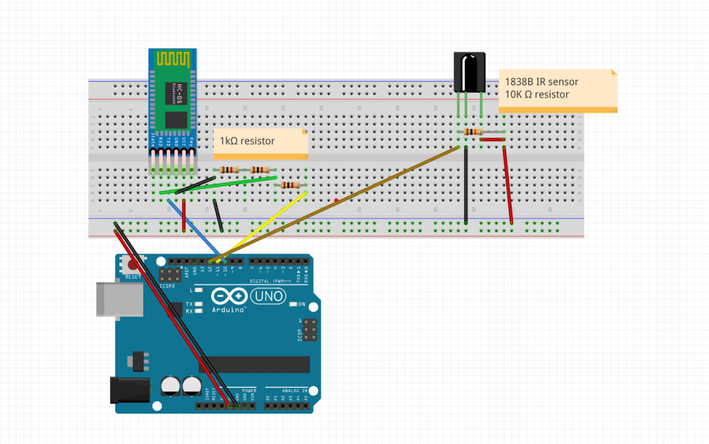
蓝牙模块和红外模块的连接
我对图片的清晰度感到抱歉,但我保证一切都在那里。
至于代码,它是非常简单的。
/*
    IR remote keypad
   0 : FF6897
   1 : FF18E7
   2 : FF6897
   3 : FF7A85
   4 : FF10EF
   5 : FF38C7
   6 : FF5AA5

*/

#include <IRremote.h>
#include <SoftwareSerial.h>
SoftwareSerial EEBlue(10, 11); // RX | TX


int RECV_PIN = 12;        // Infrared receiving pin
IRrecv irrecv(RECV_PIN); // Create a class object used to receive class
decode_results results; // Create a decoding results class object

void setup()
{
  Serial.begin(9600); // Initialize the serial port and set the baud rate to 9600
  Serial.println("UNO is ready!");  // Print the string "UNO is ready!"
  irrecv.enableIRIn(); // Start the receiver
  EEBlue.begin(9600);
}


char value_to_char(unsigned long val)
{
  if (val == 16738455)
    return '0';
  else if (val == 16724175)
    return '1';
  else if (val == 16718055)
    return '2';
  else if (val == 16743045)
    return '3';
  else if (val == 16716015)
    return '4';
  else if (val == 16726215)
    return '5';
  else if (val == 16734885)
    return '6';
  else if (val == 4294967295)
    return 'X';
  else
    return '?';


}

void loop() {

// if we recieve an IR message, send it via the bluetooth module.
  if (irrecv.decode(&results)) {
    // Waiting for decoding
    Serial.println(results.value); // Print out the decoded results
    Serial.println(value_to_char(results.value)); // Print out the corresponding character

    EEBlue.write(value_to_char(results.value));

    irrecv.resume(); // Receive the next value
  }

  // Feed any data from bluetooth to Terminal.
  if (EEBlue.available())
  {
    Serial.println(EEBlue.read());
  }

  // Feed all data from termial to bluetooth
  if (Serial.available())
    EEBlue.write(Serial.read());

  delay(100);

}
为了测试一切,我使用了一个叫做 "蓝牙终端HC-05 "的应用程序,它基本上允许你从HC-05发送和接收数据。当你在硬件方面工作,不想花时间做一个快速和肮脏的应用程序来接收蓝牙数据时,这是一个救星。
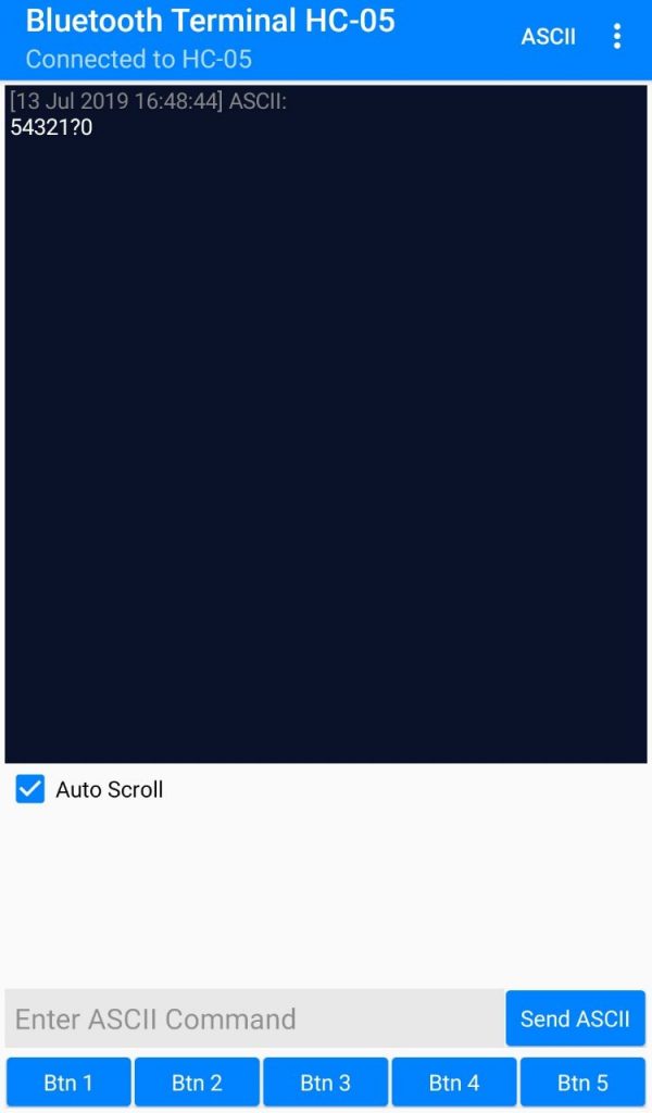
它的作用!
最后的arduino设置
我写了一整篇关于这个问题的文章,你可以在这里找到!所以我将跳过关于如何设置它的细节。直接说我如何使用它。
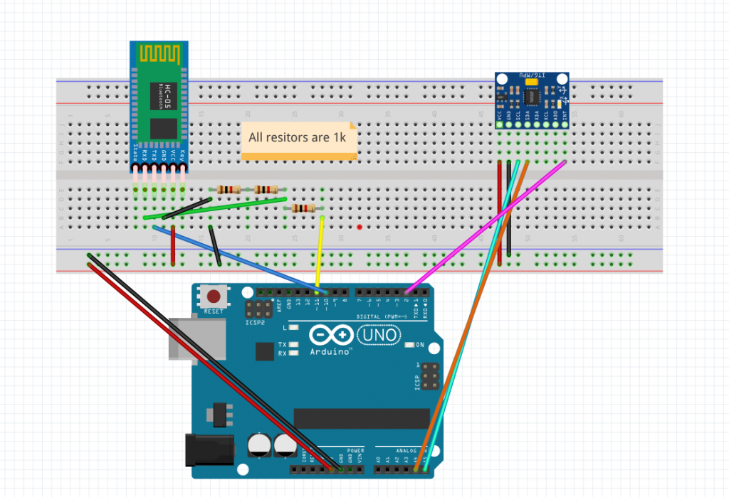
这里是硬件方面的 "最终 "设置。 至于代码,现在所要做的就是找到立方体每一面的所有x/y/z值。但是我还没有一个立方体,而且arduino UNO板太大。所以现在我打算做第一个概念证明,时间追踪器只有两面:如果板子指向左边或右边,就登记。
经过几次测试,我意识到获得一致的读数并不像我想象的那样容易,在Z值上有一个不可忽略的漂移。但是现在我只关心x值,因为我想知道电路板是指向左边(x ~= -80)还是右边(x ~= 80)。
这就转化为这段代码。
#include <SoftwareSerial.h>
#include <MPU6050_tockn.h>
#include <Wire.h>
MPU6050 mpu6050(Wire);
SoftwareSerial EEBlue(10, 11); // RX | TX
int pos = 0; // unset = 0, left = 1, right = 2

void setup()
{
  Serial.begin(9600); // Initialize the serial port and set the baud rate to 9600
  Serial.println("UNO is ready!");  // Print the string "UNO is ready!"
  Wire.begin();
  mpu6050.begin();
  // offsets that I previously calculated using mpu6050.calcGyroOffsets(true);
  mpu6050.setGyroOffsets(-1.58, 0.69, -1.71);
  EEBlue.begin(9600);
}


void loop() {

  mpu6050.update();
  float x = mpu6050.getAngleX();
  float y = mpu6050.getAngleY();

  if (x < -50)
  {
    if (pos <= 1)
    {
      EEBlue.write("right\n");
      pos = 2;
    }
  }
  else if (x > 50)
  {
    if (pos == 0 || pos == 2)
    {
      EEBlue.write("left\n");
      pos = 1;
    }

  }

  Serial.println(x);

  Serial.println(pos);
}
很简单吧?下面是整个系统的一个小演示。
数据通过蓝牙发送到手机上,如果
该视频不工作,可以试试这个 链接
。
所以现在我们有了一个系统,可以向配对的手机发送数据并检测方向!成功了 现在剩下的就是把代码移植到生产板上,3D打印一个立方体,把所有的东西都装进去,得到每个面的位置数据(面1是x/y,面2是x1,y1等等...),我们就可以在硬件方面大展身手了
The postBuilding a time tracker using arduino and blockchain tangletime part 2appeared first onMartin Lees.
