

This reading will walk you through setting up your hardware whether you purchased the TinyML Kit or your own off-the-shelf parts.
Setting up the TinyML Kit
Certainly, the easiest and most reliable way to obtain all of the parts necessary for this course is to procure the purpose-designed kit that we have developed with Arduino, available at this link for $49.99. If you ordered the official kit, then getting setup will be quick and easy. We outline the required steps below:
-
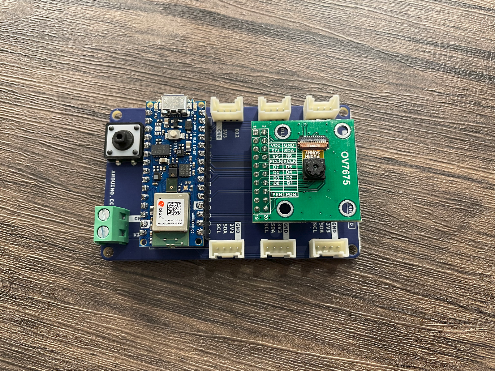
Slot the Nano 33 BLE Sense board into the Tiny Machine Learning Shield.
You’ll want to target the pair of spatially separated 1x15 female headers. Carefully align the pins of the microcontroller board with the headers below and then gently push down until the board is seated flush against the top of each header. The downward facing pins should no longer be visible. As best you can, avoid touching the components atop the board to prevent inadvertently damaging the surface mount devices. Pay attention to the orientation of the board so that the indication of the USB port on the PCB silkscreen matches the physical port on the board itself.
-
Slot the OV7675 camera module into the shield using the same technique.
You’ll want to target the 2x10 female header. Carefully align the pins of the camera module with the headers and then gently push down until the board is seated flush against the top of each header. The downward facing pins should no longer be visible. As best you can, avoid touching the camera module atop the board to prevent inadvertent damage. Pay attention to the orientation of the camera module so that the camera sensor is to the right of the header array (as shown), further from the microcontroller board than the header array.
-
Finally, use the provided USB cable (type-A to microB) to connect the Nano 33 BLE Sense development board to your machine. If your PC only features type-C USB ports, you will need to obtain an adaptor.
Note that if you are only calling upon hardware found on the Nano 33 BLE Sense development board (say the MCU and IMU), you could forgo connecting it to the Tiny Machine Learning Shield. If you need to remove either the Nano board or the camera module from the shield, grip each side of whichever board and pull back with a gentle rocking motion (back and forth) to work the pins out from the headers below.
Wiring Up Off-the-Shelf Parts
While we generally encourage all to consider Arduino’s Tiny Machine Learning kit as the primary and recommended hardware option, we understand that in certain circumstances, it may be beneficial, or even necessary, to obtain some or all of these parts via other means. If you have bought off-the-shelf components using our guide, we outline the steps you are likely to take in getting setup, below.
-
Slot the Nano 33 BLE Sense board into a solderless breadboard.
If you aren’t familiar with how breadboards can be used as a substrate for connecting various electrical components, you can take a moment to review the mechanism, here. As shown in the pictures above, we’ve targeted the left-hand side of the breadboard and seated the microcontroller board into the solderless breadboard along its length, with each of the 1x15 arrays of male pins on opposite sides of the ‘trough’ that runs through the middle of the breadboard. Given the board’s width, one side will have three rows of receptacles beside it along the board while the other will have two. Which side is of no consequence. Note also that we’ve positioned the USB port at the end of the breadboard, to facilitate connections to your PC. So, altogether, you’ll want to carefully align the pins of the microcontroller board with the receptacles below and then gently push down until the board is seated flush against the breadboard. The downward facing pins should not be visible. Avoid touching the components atop the board to prevent inadvertently damaging the surface mount devices.
-
With female-to-male jumper wire, use the following Fritzing (wiring) diagram, pinout diagrams, and connection table to link the OV7675 camera module to the microcontroller board via the solderless breadboard.
You can start by isolating (tearing away, as applicable) 20 adjoined female-to-male jumper wires as shown in the first photo above. For clarity, keep the desired 20 wires connected together, but tear away any number above this. The sequence of colors is of no consequence. Next connect the female side of this wire assembly to the male pins of the camera module in an alternating pattern. To keep track of what each color represents, it may be easiest to have the left or right-most color in your wire assembly connect to pin 1, where the next color in your sequence connects to 2, and so on. That way, the camera module’s pinout is now encoded by the sequence of colors.
-
Our next step will be to connect the camera module pinout (1-20) to specific pins on the microcontroller board via the solderless breadboard.
Below we’ve mapped these OV7675 module pin numbers onto a fritzing (wiring) diagram for the Arduino Nano 33 BLE sense (assuming it is placed into a breadboard):
In case also helpful, we have also included the full pinout (designation) for the Nano 33 BLE Sense development board below as well as a table explaining the full pin connections needed from the OV7675 to the Arduino Nano 33 BLE Sense:
| Description | Camera Module Pin | Microcontroller Board Pin |
|---|---|---|
| VCC / 3.3V | 1 | 3.3V |
| GND | 2 | GND |
| SIOC / SCL | 3 | SCL / A5 |
| SIOD / SDA | 4 | SDA / A4 |
| VSYNC / VS | 5 | D8 |
| HREF / HS | 6 | A1 |
| PCLK | 7 | A0 |
| XCLK | 8 | D9 |
| D7 | 9 | D4 |
| D6 | 10 | D6 |
| D5 | 11 | D5 |
| D4 | 12 | D3 |
| D3 | 13 | D2 |
| D2 | 14 | D0/RX |
| D1 (may be labeled D0) | 15 | D1/TX |
| D0 (may be labeled D1)¹ | 16 | D10 |
| NC | 17 | -- |
| NC | 18 | -- |
| PEN / RST | 19 | A2 |
| PWDN / PDN | 20 | A3 |
So, for example, the black wire shown in the top right of the image of the set of wires connected to the OV7675 above, is connected to the camera module’s first pin (pin #1). We can directly see on the fritzing diagram that pin #1 from the OV7675 should be connected to the second to the top left pin on the Arduino. We can also see that according to the table above, we need to connect that to the Arduino’s 3.3V pin, which we can find in the pinout diagram above as being the second pin on the top left.
Another example: the second wire (white) should then connect to either the second pin from the bottom on the left (as we marked on the fritzing diagram), or the fourth pin from the bottom on the right hand side of the MCU board, as either spot² will provide a connection to GND.
Continue down the table (or around the fritzing diagram) until all pins have been connected, outside of pins 17 and 18, which are left unconnected. We choose to include wires for these pins, even though they serve no purpose, because their presence in connecting to the camera module makes the entire cable assembly physically more robust, which is favorable in maintaining a solid connection.
We want to underline that you should take your time in this process and verify each connection as you go, because most (nearly all) of the issues reported for this camera module stem from a wire that is connected to the wrong pin - perhaps only one location off or so. Precision here for the entire table is required for functionality.
If you’re interested, the communication between the controller and the camera module is standardized as a Serial Camera Control Bus (SCCB) as well as a Camera Parallel Interface (CPI) or, equivalently, Digital Video Port (DVP).
When you are done wiring up the camera your setup should like something like the following:
- Finally, use the provided USB cable (type-A to microB) to connect the Nano 33 BLE Sense development board to your machine. If your PC only features type-C USB ports, you will need to obtain an adaptor.
It’s probably apparent why we are so excited that Arduino has developed the Tiny Machine Learning Shield for our course kits! :)
If you’ve sourced your jumper wires from SparkFun, you may be able to call on the same sequence of colors as we have above.
Changes for the OV7670 Camera Module
While the course staff will not officially support the OV7670 camera module, it exists as a viable alternative if the OV7675 is unavailable in your region. Fortunately, there is an Arduino blog post concerning using the OV7670 module for tinyML.
IMPORTANT NOTE: The connection table in the Arduino blog post is out of date, you should use the same connection table as for the OV7675 listed above. The one change is that the OV7670 only has 18 pins. Therefore, you need to omit the two NC pins between D0/D1 and RST/PWDN.
¹Be careful, the silkscreen label on some OV7675 camera modules mistakenly swaps D0 and D1!
²Note that GND, or ground, is the only example where a pin designation is repeated.
