

大家好,下面和大学一起学习如何使用顶点着色器vertex shader来做顶点变换,在我的github上有一个项目OpenGLES2.0SamplesForAndroid,我会不断地编写学习样例,文章和代码同步更新,欢迎关注,链接:github.com/kenneycode/…
在之前的例子中,我们都使用到了顶点着色器vertex shader,但只是简单地用了一下,把输入的顶点坐标又原样地输出了,没有做任何操作,这篇文章给大家介绍如何在vertex shader做顶点变换。
我们先看了解一下OpenGL的渲染管线(pipeline):
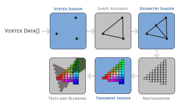
drawXXX()方法后执行的流程,我们传递的顶点首先会经过顶点着色器vertex shader的处理,一般会在里面做顶点变换相关的逻辑,然后进行图元装配,再经过几何着色器geometry shader,这个着色器相对来说使用得少一些,可暂时先忽略,然后接下来就是光栅化,所谓光栅化就是把我们要渲染的图像打碎成屏幕上的像素,因为最终要显示到屏幕上,就必须将图形对应到像素上,光栅化完成后,我们就有了要渲染的图形对应的像素,此时像素还没有颜色,需要我们填上颜色,这时就到达到了片段着色器fragment shader,在fragment shader中我们通常进行颜色的计算,确定对应的像素显示什么颜色,fragment shader将在下篇文章中介绍。
在整个渲染管线中,vertex shader、geometry shader和fragment shader这三部分是可编程分部,可编写shader代码实现相应的功能,我们目前重点关注vertex shader和fragment shader。
这里特别注意一点,我们的shader代码并不是像普通程序那样,一次性输入所有顶点,然后再输出,例如对于vertex shader,我们传递了3个顶点,并不是3个顶点一起执行一次vertex shader,而是分别对这3个顶点执行一次,也就是执行了3次。对于fragment shader也是类似的,并不是执行一次为所有的像素填充颜色,而是对每个像素都执行一次。这个特点有时让初学者感到困惑。
先来回顾一下我们简单的vertex shader:
precision mediump float;
attribute vec4 a_Position;
void main() {
    gl_Position = a_Position;
}
第一行,我们声明了这个shader使用的精度,mediump表示使用中等精度,一些对精度要求很高的应用,可以声明高精度。
第二行,我们声明了一个attribute vec4 a_Position变量,它表明这是一个attribute类型的四维向量,什么attribute类型?上文提到如果我们传递了3个顶点,就会对这3个顶点分别执行一次vertex shader,在一次执行中,这个attribute类型的变量所对应的就是这3个顶点中的某个顶点,与此相对的是uniform变量,uniform变量在所有vertex shader的执行过程中都是同一个值,在本文中我们也会遇到。
这里为什么一个顶点是四维向量?我们不是只传了二维的x、y坐标吗?在OpenGL中,顶点总是四维的,即x、y、z、w,其中x、y、z不传的话默认是0,w不传的话默认是1,w是用来做归一化(标准化)的,后续文章会有介绍。
回看我们之前《Android OpenGL ES 2.0 手把手教学(1)- Hello World!》例子,我们有这样一句:
// 指定a_Position所使用的顶点数据
// Specify the vertex data of a_Position
GLES20.glVertexAttribPointer(location, 2, GLES20.GL_FLOAT, false,0, buffer)
其中第2个参数就是指定了一个顶点有多少个成份,因此在vertex shader中,vec4 a_Position接受的只有x、y,z和w保持默认值。
我们继续往下看,vertex shader中包含一个main()方法作为入口,和很多编程语言类似。gl_Position是vertex shader的一个内置变量,表示vertex shader的输出,在我们之前的例子,是直接将输入的顶点原样又输出了,本文将对顶点做变换,先看个简单的例子:
precision mediump float;
attribute vec4 a_Position;
void main() {
    gl_Position = a_Position + vec4(0.3, 0.3, 0, 0);
}
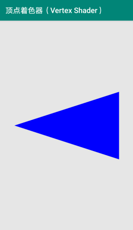
我们给顶点加上了一个偏移量,来看看效果:
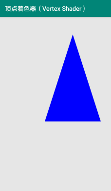
可以看到,三角形发生的偏移,接下来,我们来完善一下,将平移、缩放和旋转一起写到vertex shader中,为了计算上的方便,我们使用平移矩阵、缩放矩阵和旋转矩阵,这些矩阵的写法是数学上的知识,并不是OpenGL特有的,这里就不展开讲了,来看看加入变换矩阵后的vertex shader:
precision mediump float;
attribute vec4 a_Position;

uniform vec2 u_Translate;
uniform float u_Scale;
uniform float u_Rotate;

void main() {
   mat4 translateMatrix = mat4(1.0, 0.0, 0.0, 0.0,
                              0.0, 1.0, 0.0, 0.0,
                              0.0, 0.0, 1.0, 0.0,
                              u_Translate.x, u_Translate.y, 0.0, 1.0);
   mat4 scaleMatrix = mat4(u_Scale, 0.0, 0.0, 0.0,
                        0.0, u_Scale, 0.0, 0.0,
                        0.0, 0.0, 1.0, 0.0,
                        0.0, 0.0, 0.0, 1.0);
   mat4 rotateMatrix = mat4(cos(u_Rotate), sin(u_Rotate), 0.0, 0.0,
                         -sin(u_Rotate), cos(u_Rotate), 0.0, 0.0,
                         0.0, 0.0, 1.0, 0.0,
                         0.0, 0.0, 0.0, 1.0);
    gl_Position = translateMatrix * rotateMatrix * scaleMatrix * a_Position;
}
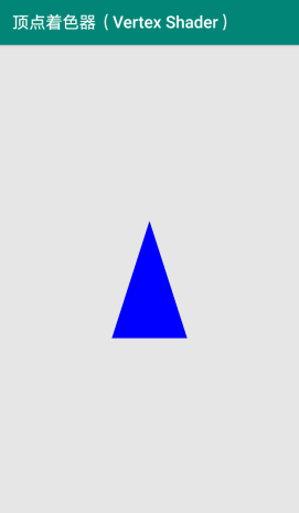
我们向vertex shader中传递平移量u_Translate、缩放量u_Scale和旋转量u_Rotate(单位是弧度),前面演示过了平移,下面我们利用这个vertex shader来演示缩放,将u_Scale设置为0.5,平移和旋转设置为0:
// 获取字段u_Offset在shader中的位置
// Get the location of translate in the shader
val uTranslateLocation = GLES20.glGetUniformLocation(programId, "u_Translate")

// 启动对应位置的参数
// Enable the parameter of the location
GLES20.glEnableVertexAttribArray(uTranslateLocation)

// 指定u_Offset所使用的顶点数据
// Specify the vertex data of translate
GLES20.glUniform2f(uTranslateLocation, 0f, 0f)

// 获取字段u_Offset在shader中的位置
// Get the location of u_Scale in the shader
val uScaleLocation = GLES20.glGetUniformLocation(programId, "u_Scale")

// 启动对应位置的参数
// Enable the parameter of the location
GLES20.glEnableVertexAttribArray(uScaleLocation)

// 指定u_Scale所使用的顶点数据
// Specify the vertex data of u_Scale
GLES20.glUniform1f(uScaleLocation, 0.5f)

// 获取字段u_Offset在shader中的位置
// Get the location of u_Rotate in the shader
val uRotateLocation = GLES20.glGetUniformLocation(programId, "u_Rotate")

// 启动对应位置的参数
// Enable the parameter of the location
GLES20.glEnableVertexAttribArray(uRotateLocation)

// 指定u_Rotate所使用的顶点数据
// Specify the vertex data of u_Rotate
GLES20.glUniform1f(uRotateLocation, Math.toRadians(0.0).toFloat())
来看看效果:
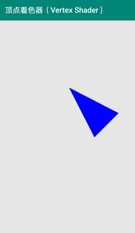
我们再来看看让它旋转90度,平移设为0,缩放设为1:
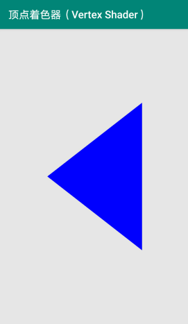
奇怪,旋转是旋转了,但为什么感觉形状变了呢?在第一篇文章中有提到过,我们直接给gl_Position传递坐标的话,这时就相当于是传了设备标准化坐标,也就是x和y的取值范围都是-1~1,而宽比长要小,同样的一个值在x轴上就显示小一些,比如(0, 0.5)这个点,旋转90度后变成(-0.5, 0),x轴上的0.5比y轴上的0.5要短些,可以做些简单的换算,让它变得正常,我们传入GLSurfaceView宽高比,来做换算:
precision mediump float;
attribute vec4 a_Position;

uniform vec2 u_Translate;
uniform float u_Scale;
uniform float u_Rotate;
uniform float u_Ratio;

void main() {
    vec4 p = a_Position;
    p.y = p.y / u_Ratio;
    mat4 translateMatrix = mat4(1.0, 0.0, 0.0, 0.0,
                              0.0, 1.0, 0.0, 0.0,
                              0.0, 0.0, 1.0, 0.0,
                              u_Translate.x, u_Translate.y, 0.0, 1.0);
    mat4 scaleMatrix = mat4(u_Scale, 0.0, 0.0, 0.0,
                        0.0, u_Scale, 0.0, 0.0,
                        0.0, 0.0, 1.0, 0.0,
                        0.0, 0.0, 0.0, 1.0);
    mat4 rotateMatrix = mat4(cos(u_Rotate), sin(u_Rotate), 0.0, 0.0,
                         -sin(u_Rotate), cos(u_Rotate), 0.0, 0.0,
                         0.0, 0.0, 1.0, 0.0,
                         0.0, 0.0, 0.0, 1.0);
    p = translateMatrix * rotateMatrix * scaleMatrix * p;
    p.y = p.y * u_Ratio;
    gl_Position = p;
}
// 获取字段u_Ratio在shader中的位置
// Get the location of u_Rotate in the shader
val uRatioLocation = GLES20.glGetUniformLocation(programId, "u_Ratio")

// 启动对应位置的参数
// Enable the parameter of the location
GLES20.glEnableVertexAttribArray(uRatioLocation)

// 指定u_Ratio所使用的顶点数据
// Specify the vertex data of u_Ratio
GLES20.glUniform1f(uRatioLocation, glSurfaceViewWidth * 1.0f / glSurfaceViewHeight)
现在再看看效果:
现在就正常了。
我们来做一下组合,将平移设为(0.3, 0.3),缩放设为0.5,旋转设为45度,看看效果:
代码在我github的OpenGLES2.0SamplesForAndroid项目中,本文对应的是SampleVertexShader,项目链接:github.com/kenneycode/…
感谢阅读!
